RF & Wireless Systems · Hardware
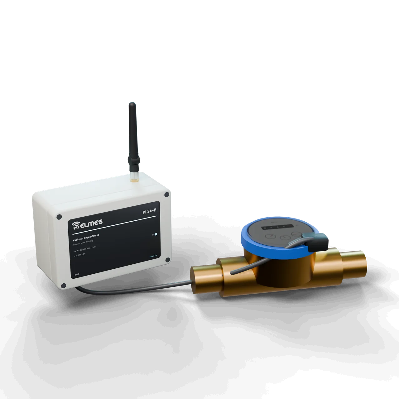
Wireless Meter Reading Node
Wireless pulse collection from water and electricity meters — years on a battery.
Overview
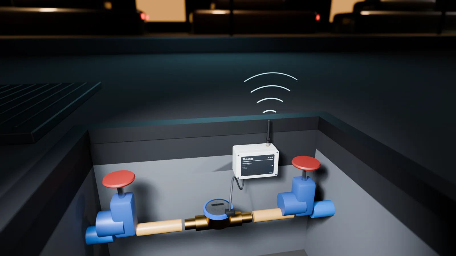
The problem. Water utilities and organized industrial zones read hundreds of meters by hand: late bills, reading errors, trouble getting into meter pits and basements. Non-revenue water (NRW) analysis requires district inlet meters and subscriber totals to be read over the same time window, which monthly manual reading cannot deliver. In factories, energy, water and compressed-air consumption cannot be tracked per line; the meters have S0 outputs, but no cable was ever run. Off-the-shelf LoRaWAN meter modules require an operator subscription and a closed platform, and nothing can be done in the field apart from changing the battery.
The solution. The node connects to the meter's S0/reed pulse output; it counts pulses (debounced, 4 independent inputs), keeps the totals in non-volatile memory and, at a configured interval (e.g. 15 min / 1 hour), sends the total, interval flow, battery and RSSI over LoRa to the gateway (Wireless Gateway / RTU). The gateway passes the data to SCADA or to the Telemetry & Process Intelligence platform as Modbus, MQTT or CSV.
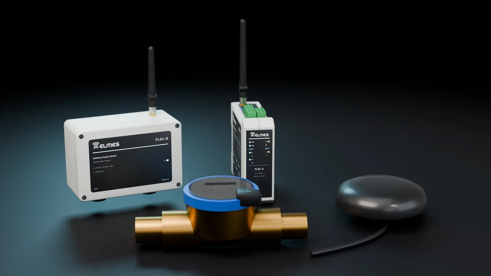
Versions. The battery version is designed to run in a meter pit for years; the mains-powered version sits on a DIN rail with a threshold relay (e.g. a leak alarm when the night-flow threshold is exceeded). To prevent data loss, the node is intended to keep its latest reports and the gateway to re-request missing intervals. Where continuous analog or contact signals must be carried, the Wireless Analog & Digital Data Link is used; the two products share the same pulse-input platform.
This product is in development or field testing. Contact us for technical information, pilot use and a preliminary quotation.
Features
- 4 independent counters, persistent totals: values survive power cuts and battery changes.
- Interval flow + total: synchronized district readings for NRW analysis (gateway time sync).
- Event reports: threshold violations and low battery are reported immediately.
- Battery life management: reporting interval and power profile are set in the field; reports thin out automatically on low battery.
- Relays on the mains version: local threshold alarm or valve shut-off when a leak is detected.
- Gateway integration: Modbus TCP register map, MQTT JSON, CSV.
- Optional: 868 MHz version, analog input (pressure), repeater.
- TargetGap recovery: buffering on the node, re-requests from the gateway.
- TargetReverse-flow and tamper detection: via a second reed input and a lid contact.
- TargetCloud monitoring: through Telemetry & Process Intelligence.
- TargetLoRaWAN compatibility mode: under evaluation.
Variants
| Model code | Supply | Inputs | Outputs | Housing | Use | Request information |
|---|---|---|---|---|---|---|
| PLS4-B | Battery (Li-SOCl2 2× C or D; 3.6 V) | 4× S0/reed | — | IP67 box, meter pit | Water utility, remote meter | Request information: PLS4-B |
| PLS4-D | 9–36 VDC (DIN rail) | 4× S0/reed, 10 kHz | 2× relay (threshold / alarm) | DIN, 2 modules | Industrial zone, factory, energy analyzer S0 | Request information: PLS4-D |
| PLS4-B-868 | Battery | 4× S0/reed | — | IP67 | 868 MHz version, export | Request information: PLS4-B-868 |
| PLS4-D-GW | 9–36 VDC | 4× S0/reed | 2× relay + Wi-Fi / Ethernet | DIN, 6 modules | Single box with gateway (small sites) | Request information: PLS4-D-GW |
Specifications
Values marked “Target” are design targets, next-generation values or chip-vendor data; they are updated as measurement and certification are completed.
| Frequency band | 433.05–434.79 MHz, 8 channels (SX1268); 868 MHz version (SX1262) |
|---|---|
| Output power | +22 dBm max.; +14…+20 dBm in the battery profile |
| Receiver sensitivity | −129 dBm @ SF11 (chip datasheet) |
| Modulation / packet | LoRa SF7–SF12; report packet ≤ 32 bytes |
| Antenna connector | u.FL → box-mounted SMA (battery IP67) / board-mounted SMA (DIN) |
| Open field | ≥ 3000 m (SF10, outdoor omni antenna 2 dBi, gateway at 6 m)Target |
|---|---|
| Meter pit → gateway | ≥ 500 m (with a pit-lid antenna)Target |
| Encryption | AES-128-CCM, NetID + 16-bit address, sequence numberTarget |
|---|---|
| Pairing | By UID to the gateway list (service tool / gateway web interface) |
| Systems on the same site | ≥ 8 via channel × NetID |
| Reporting interval | 1 min–24 h, adjustable; event reports immediately |
|---|---|
| Offline detection | 3 reporting intervals (at the gateway) |
| Watchdog | Independent hardware watchdog (IWDG) |
| Battery (PLS4-B) | Li-SOCl2 3.6 V, 2× C (2× 8.5 Ah) or D; sleep < 10 µA; ~120 mA × 100 ms per report |
|---|---|
| Battery life | ≥ 5 years at hourly reports and ≤ 1 Hz pulses (estimated with the SDK calculator)Target |
| Mains powered (PLS4-D) | 9–36 VDC, reverse-polarity + TVS protection; ~40 mA @ 12 V standby, +70 mA per relay |
| Pulse inputs | 4× S0 (IEC 62053-31 class A/B interface: 27 V / 27 mA limit) or reed / dry contact; selectable pull-up; 2–20 ms debounce; max. 10 kHz (DIN) / 100 Hz (battery) |
|---|---|
| Counters | 4× 32-bit persistent counters (FRAM / Flash); pulse/liter or pulse/kWh factor set at the gateway |
| Relay outputs | 2× relay 5 A (DIN version): threshold / alarm |
| Other inputs | Tamper / lid contact, reverse flow (2nd reed)Target |
| Communication | Service UART / SWD; gateway: Modbus TCP (register map), MQTT (JSON), CSV |
| Housing | Battery: IP67 polycarbonate, 2 cable glands; DIN: 2-module (36 mm) rail housing |
|---|---|
| Battery housing size | ~120 × 80 × 55 mmTarget |
| Mounting | Meter-pit wall / next to the meter / DIN rail |
| Operating / storage | −30…+60 °C (Li-SOCl2) / −40…+85 °C; 100 % humidity (IP67, condensation in the pit) |
| Warranty | 2 years; battery is a consumableTarget |
|---|
Applications
- Utility subscriber meters
- DMA district inlet meters
- Non-revenue water (NRW) analysis
- Industrial zone and estate sub-meters
- Shared cost allocation
- Factory energy and compressed air
- Production counters
- Agricultural well meters
- Solar plant production meters (S0)
- Water utilities: subscriber meters, DMA district inlet meters and non-revenue water (NRW) analysis. Leaks are detected by comparing district inlet meters with subscriber totals over the same interval and by a minimum night-flow threshold; the analysis is targeted on Telemetry & Process Intelligence.
- Industrial zones and housing estates: water, electricity and gas sub-meters; shared cost allocation.
- Factories: per-line energy (the analyzer's S0 output), compressed air and water; production counting from machine pulses.
- Agriculture and irrigation: well meters and water quota tracking, together with Wireless Irrigation Control System sites.
- Energy: the S0 output of production meters at small solar plants.
Experience with wireless monitoring at well and reservoir sites comes from the Wireless Well & Reservoir Control System.
Compliance & documentation
The product is at design stage. The datasheet, manual, Modbus register map, MQTT schema and test documents will be prepared according to the plan below. The node is not a meter but a pulse collector; legal metrology stays with the meter.
- TargetCE – RED 2014/53/EU (EN 300 220-2, EN 301 489-1/-3)Step by step, starting at module level
- TargetEMC – EN 61000-6-2 / EN 61000-6-4
- TargetRoHS declaration
- TargetUN 38.3 — Li-SOCl2 battery transport document
- Out of scopeMID 2014/32/EUMeasurement stays with the meter and the node only collects pulses; billing use may require utility approval
- TargetCE declaration of conformity and user manual
Frequently asked questions
Which meters does it work with?
Any water, electricity, gas or heat meter and any production counter with an S0 (open-collector) or reed/dry-contact pulse output. Mechanical meters without a pulse output are fitted with the meter manufacturer's reed sensor.
Can it be used for billing?
The node relays the meter's pulses; legal metrology stays with the meter (MID). Billing integration depends on the utility's approval process.
How long does the battery last?
The target is ≥ 5 years with hourly reports and a low pulse rate. Reporting frequency and pulse rate determine the lifetime; low battery shows up in the reports.
Will the signal get out of a meter pit?
With a plastic lid, usually yes; with a metal lid an external antenna is required. The pit-to-gateway range is verified on site, and a repeater is used if needed.
How many nodes can one gateway handle?
The target is ≥ 200 nodes at hourly reporting; more frequent reporting lowers the number, and extra channels or gateways scale it up.
Where does the data go?
To your own gateway (Modbus TCP / MQTT / CSV), with optional cloud monitoring through Telemetry & Process Intelligence. There is no operator subscription.
Is data lost if communication drops?
Totals are kept persistently on the node. The node is intended to store its latest reports, and the gateway to re-request the gaps once the link is back.
How is leak detection done?
By comparing district inlet meters with subscriber totals over the same interval (NRW) and with a minimum night-flow threshold. The analysis is targeted on Telemetry & Process Intelligence.
Can it carry continuous analog signals too?
The node is designed for pulse collection; an analog input (e.g. pressure) is only an option. For continuous 4–20 mA or contact signal transfer, use the Wireless Analog & Digital Data Link.
What about the warranty?
A 2-year warranty is planned; the battery is a consumable.
Get information about this product
Our engineering team replies within 24 hours.
Related products
 Coming soonModules, Boards & Gateways
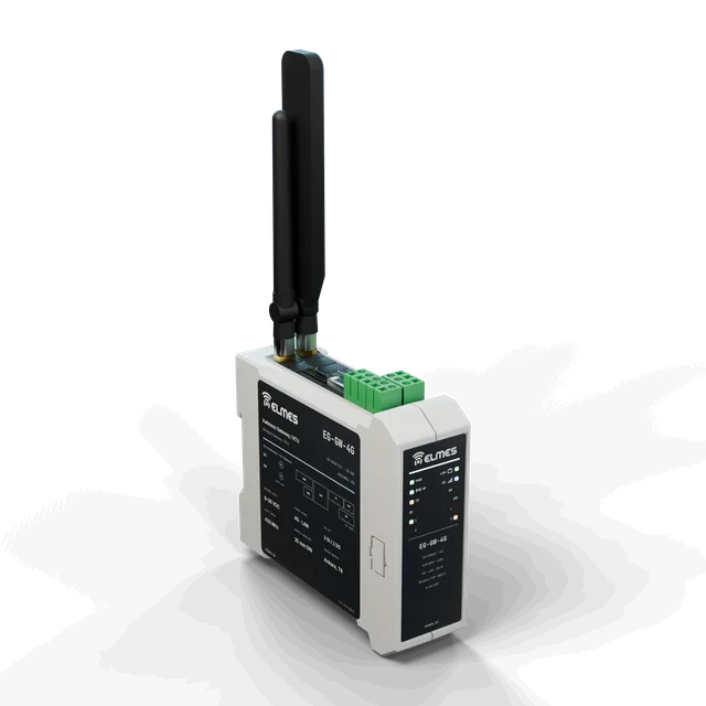
Wireless Gateway / RTU
Connect every LoRa node in the field to SCADA, the cloud and PLCs with a single box.
View details: Wireless Gateway / RTU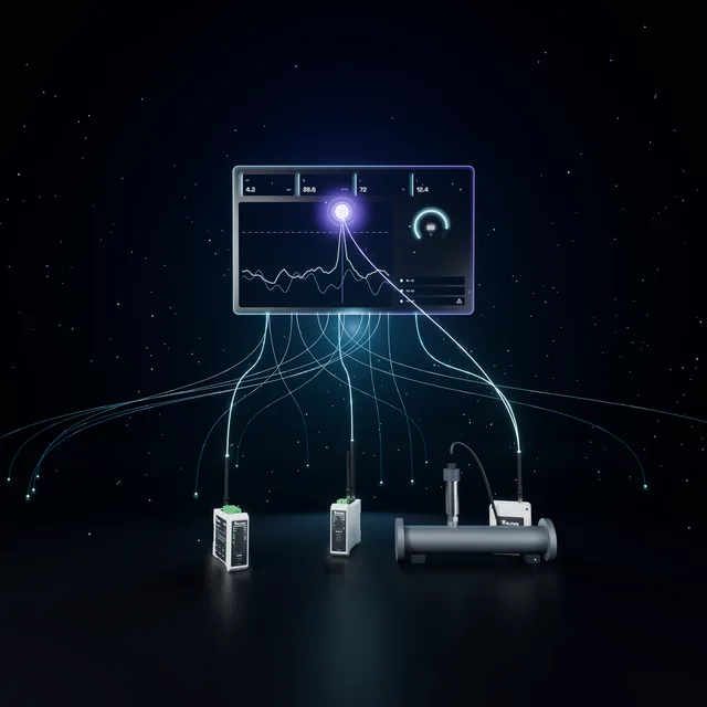 Coming soonAutomation & Telemetry
Telemetry & Process Intelligence
Field data into semantic memory, semantic memory into decisions.
Early access / pilot
View details: Telemetry & Process Intelligence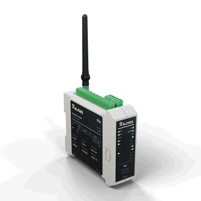 RF & Wireless Systems
Wireless Analog & Digital Data Link
Carry 4–20 mA / 0–10 V signals wirelessly.
View details: Wireless Analog & Digital Data Link