Measurement & Balancing · Hardware
VibroBal — Portable Vibration Analyzer & Field Balancer
Measure the rotor in place, balance it in place.
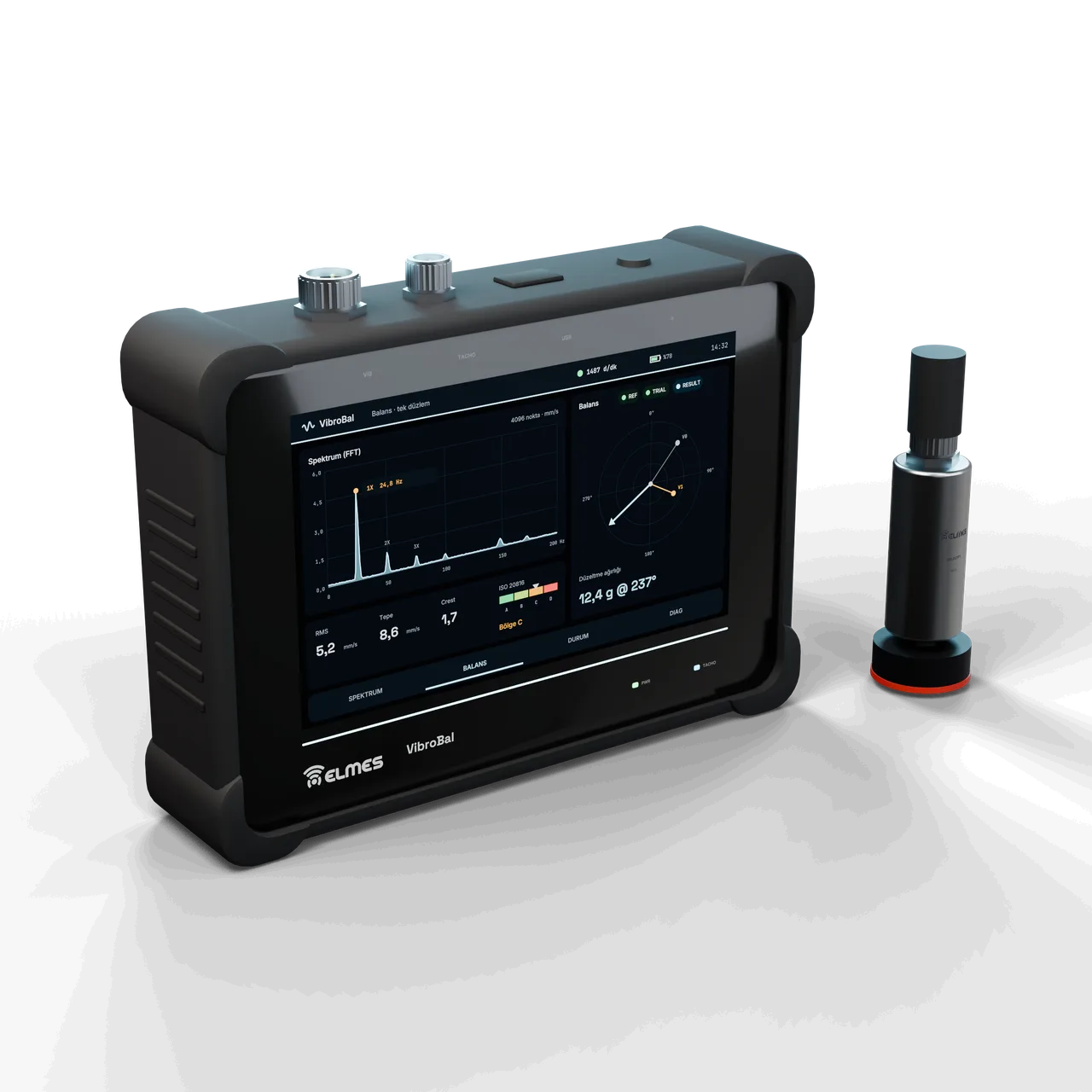
Overview
The problem. Imbalance in fans, pumps, motors and rotors is the most common source of vibration in industry. To balance a rotor in the field without removing it, plants use imported vibration analyzers (VIBXPERT II class); being multi-channel and multi-function, these are expensive and come with neither a Turkish interface nor local service. Yet balancing services and maintenance teams need only “1X amplitude + phase + single-plane correction” for most jobs.
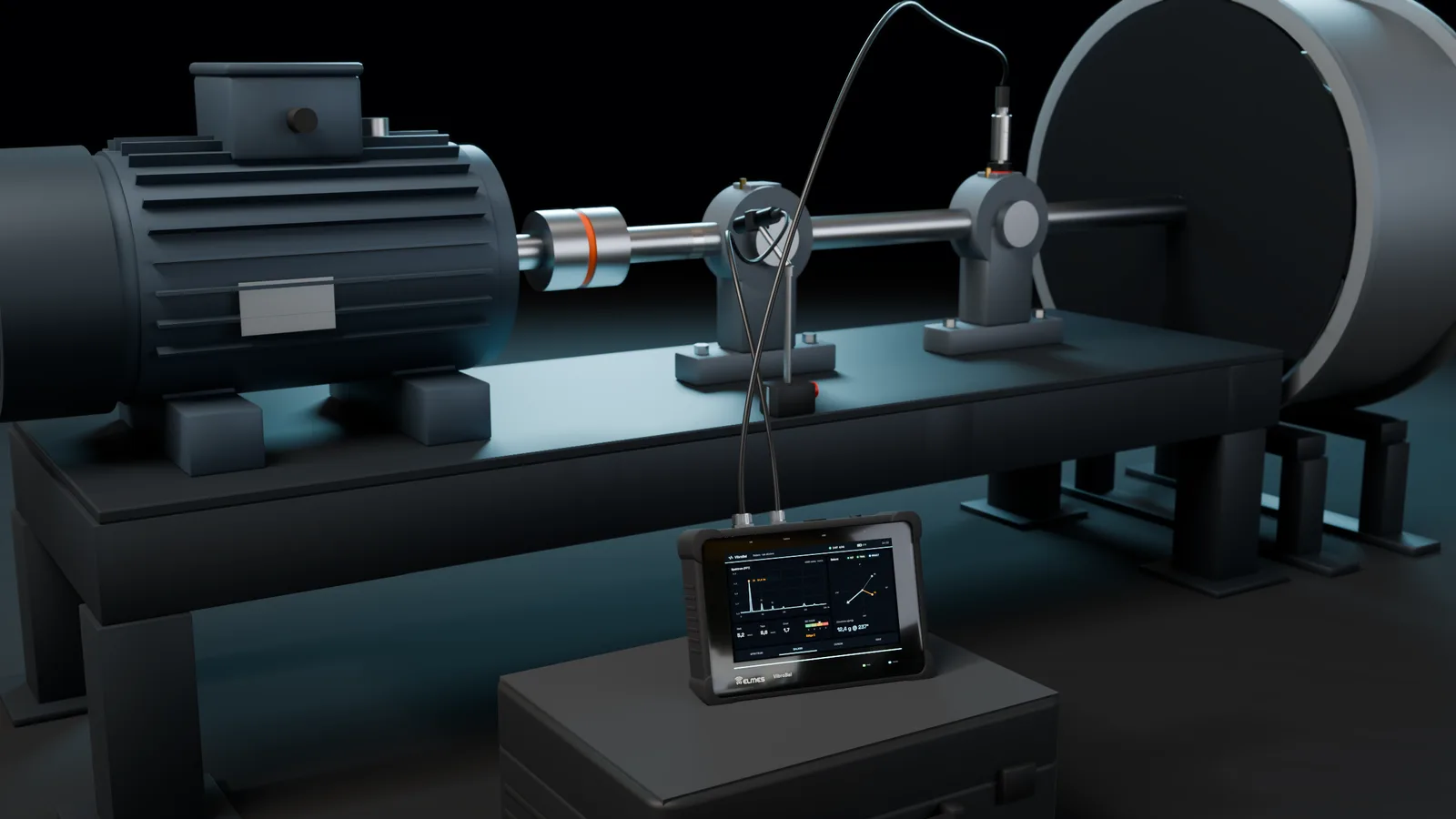
The solution. VibroBal measures 1X amplitude and phase with a single vibration sensor and an optical tachometer, and a guided wizard (reference run → trial weight → result) gives the correction weight in grams and degrees. The same device shows machine condition with a spectrum (4096 points), time waveform, RMS/peak/crest values and ISO 20816 zone colors. The programmable analog front end selects gain and anti-alias filtering automatically, so the operator never has to deal with signal levels.
Positioning. The aim is not to replace the VIBXPERT II but to cover the most frequently performed subset of its jobs with an affordable, locally made device. Two-plane balancing and multi-channel measurement are out of scope; those jobs are left to a balancing-machine measurement system.
| Imported multi-channel analyzer (VIBXPERT II class) | Manual calculation + general-purpose scope/multimeter | VibroBal | |
|---|---|---|---|
| Channels / planes | 2+ channels, 2 planes | — | 1 channel, 1 plane |
| Balancing wizard | Yes | No (manual vector math) | Yes, guided |
| Spectrum / ISO zones | Yes | No | Yes |
| Interface / service | English, service abroad | — | Turkish interface (on the roadmap), service in Ankara |
| Price class | High | — | Mid-range |
This product is in development or field testing. Contact us for technical information, pilot use and a preliminary quotation.
Features
- Guided single-plane balancing wizard: REF → TRIAL → RESULT; CAPTURE is enabled only for a valid, unsaturated, phase-synchronous measurement; the suggested trial weight is ~10 % of rotor mass.
- AUTO front end: gain set by headroom, the tightest analog filter chosen from 1X; AUTO is frozen during the balancing wizard so that V0 and V1 pass through the same path.
- Rotor-wait mode: the reference is kept while the motor is stopped and the weight is fitted.
- Spike discrimination: saturation is judged on the filtered signal; the raw rail-sample count is shown on the DIAG screen (a hint of mechanical knocks/EMI).
- Tachometer-referenced time-domain angle: FFT and time-domain markers agree on the polar display.
- Spectrum and condition display: 4096-point FFT, time waveform, RMS/peak/crest and ISO 20816 zone colors.
- DIAG screen: headroom percentage, gain/filter index, battery, speed stability.
- Sensor calibration: without calibration the display marks estimated values as “ISO~”; once a calibration table is entered, it shows true units.
- Simulation mode: training and demos without a sensor.
- TargetRoadmap: synchronous averaging, envelope analysis + bearing fault frequency calculator (BPFO/BPFI/BSF/FTF), order tracking, Bode/Nyquist run-up/coast-down, cepstrum, ISO 1940 balance quality grade, split weights, job archive, Turkish interface, on-screen keyboard.
Variants
| Model code | Contents | Sensor | Status | Request information |
|---|---|---|---|---|
| VB-1 | Device (7" touchscreen, analog front end, battery), tachometer input | Sensor sold separately | In field testing | Request information: VB-1 |
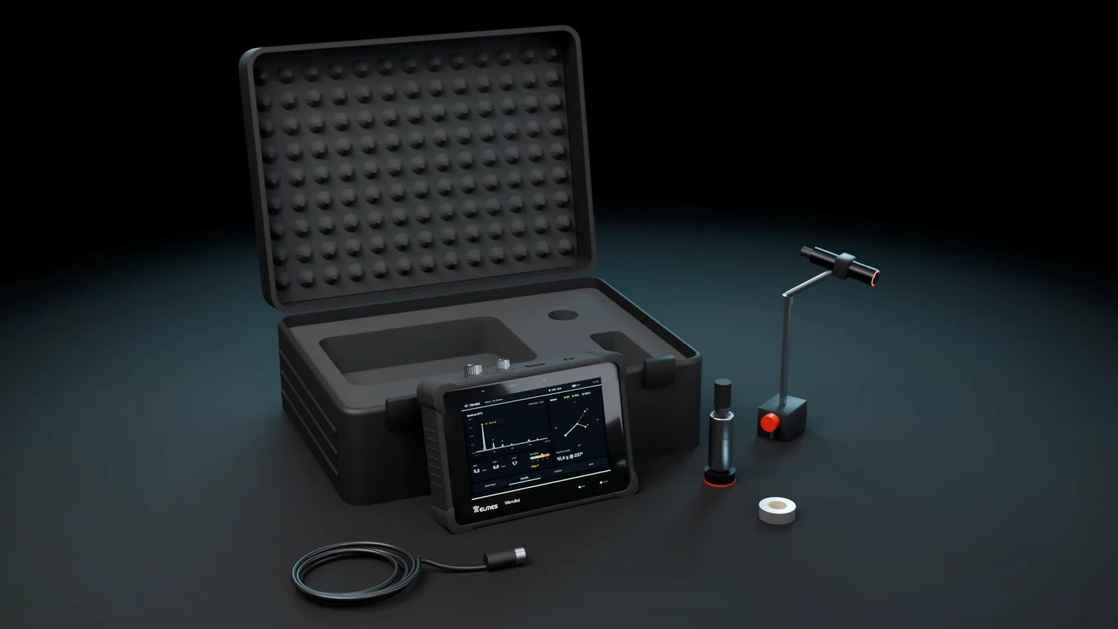
| VB-1-KTarget | VB-1 + electrodynamic vibration velocity sensor + optical tachometer + carrying case | Elmes electrodynamic velocity sensor | Planned | Request information: VB-1-K |
| VB-1-IEPETarget | VB-1 + IEPE adapter module (for industrial accelerometers) | 100 mV/g IEPE | Planned (requires a separate front-end module) | Request information: VB-1-IEPE |
| VB-2 | Two channels / two planes | — | Not planned (single-plane device) | Request information: VB-2 |
Specifications
Values marked “Target” are design targets, next-generation values or chip-vendor data; they are updated as measurement and certification are completed.
| Vibration input | 1 channel, passive velocity / piezo voltage sensor, AC-coupled, 47 kΩ input; no IEPE supply |
|---|---|
| Speed measurement | RPM from the tachometer; speed check at the end of each window (> 2 % deviation is rejected) |
| Speed range | Field-tested at 673–1500 rpm |
| Balancing | Single-plane influence-coefficient method; result in grams @ degrees |
| Vibration velocity | mm/s RMS; today raw counts + analytical mm/s estimate (assuming 4.0 mV/(mm/s)) |
| Unit selector | m/s², g, mm/s, milTarget |
| Analysis band | 0–3.4 kHz (54.878 kHz / 8 decimation → 6.86 kHz sampling) |
| ISO band limiting | 10–1000 HzTarget |
| Amplitude error (signal processing) | ≤ 0.025 % (Hanning + Grandke + scallop correction; with synthetic signals) |
| Absolute accuracy | ±5 % (depends on sensor calibration)Target |
| Phase error | ≤ 0.043° on the FFT side (with synthetic signals); time-domain indicator 1.406°/bin |
| FFT resolution | 4096 points, 1.675 Hz/bin, 0.597 s window |
| ADC | 12-bit, 54.878 kHz, ×8 decimation, 32768 samples per window |
| Sampling stream | Single buffer (field version) |
| Gapless sampling | Double bufferingTarget |
| Gain | 4 steps (×2.87 / ×3.51 / ×5.32 / ×10.6) + AUTO |
|---|---|
| Anti-alias filter | 4 steps (1 / 10 / 22 / 47 nF) + AUTO |
| Tachometer | 1 optical sensor input, timer capture |
| Display | 7" touchscreen |
| PC connection | USB-CDC log |
| Data export | CSVTarget |
| Supply | 7.2 V battery input; LM2576 → 5 V → 3.3 V; battery measured by the ADC (×11 divider) |
|---|---|
| Battery runtime | ≥ 6 hoursTarget |
| Enclosure | Handheld enclosure, IP54Target |
|---|---|
| Operating temperature | 0…+50 °CTarget |
| Warranty | 2 yearsTarget |
|---|---|
| Service | Ankara, Türkiye |
Applications
- Fans and exhaust fans
- Pumps
- Electric motors
- Compressors
- Field balancing services
- Final inspection in rotor production
- Spot checks beside balancing machines
- Predictive maintenance rounds
Industries: cement, textiles, food, energy (cooling towers), HVAC, machine building.
Typical balancing flow: reference run (REF) → trial weight (TRIAL; suggested ~10 % of rotor mass) → result (RESULT, grams @ degrees). While the motor is stopped and the weight is fitted, the device waits in a “waiting for rotor” state and keeps the reference. Phase and balancing require the tachometer; spectrum/RMS measurement alone does not.
Predictive maintenance: machine condition is tracked on periodic rounds through ISO 20816 zone monitoring.
Out of scope: two-plane balancing and multi-channel measurement; a balancing-machine measurement system is recommended for those jobs.
Compliance & documentation
The device is in field testing; its documentation set is being prepared according to the plan below.
- TargetCE declaration of conformity (EMC / LVD)
- TargetISO 20816 / ISO 1940 conformity note
- TargetCalibration procedure
- TargetUser manual
Frequently asked questions
Which sensors does it work with?
A passive velocity sensor or a piezo sensor with voltage output connects directly; a kit with the Elmes electrodynamic velocity sensor (VB-1-K) is planned. IEPE accelerometers need a separate adapter module (VB-1-IEPE, planned).
Can it do two-plane balancing?
No; it is a single-plane balancer. Two-plane jobs call for a balancing-machine measurement system.
Is the tachometer mandatory?
For phase and balancing, yes. For spectrum/RMS alone, no.
Is the reference lost when I stop the motor to fit a weight?
No; the device switches to a “waiting for rotor” state and keeps the reference.
Are the mm/s readings accurate?
Without sensor calibration the display shows “ISO~” (estimated); once a calibration table is entered, it shows true units.
Can I transfer data to a PC?
Today through a USB-CDC log; CSV export is on the roadmap.
Does it replace analyzers such as the VIBXPERT II?
No; the aim is to cover the most frequent subset of the work done with that class of device — 1X amplitude, phase and single-plane balancing — with an affordable, locally made instrument. Multi-channel measurement and two-plane balancing are out of scope.
What about warranty and service?
A 2-year warranty is planned; service is in Ankara.
Get information about this product
Our engineering team replies within 24 hours.