RF & Wireless Systems · Hardware
Wireless Digital I/O Link — 8 Channels
8 relays, 8 inputs — replace the cable with RF.
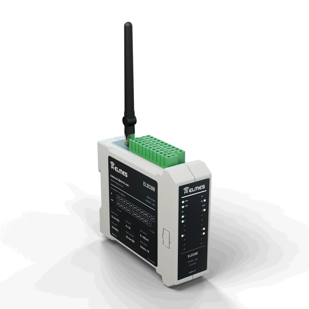
Overview
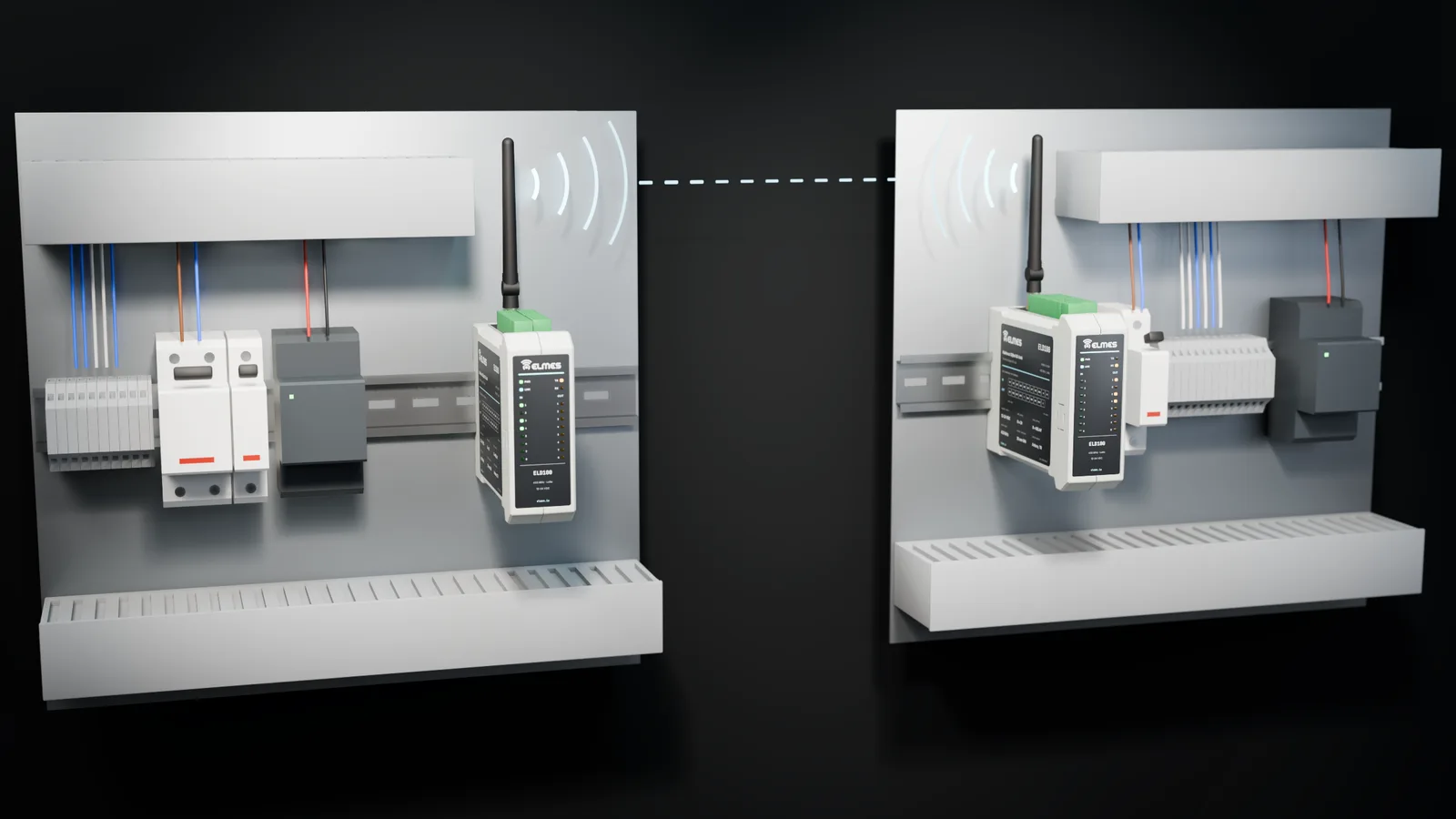
The problem. Carrying a few dry contacts between a pump and a tank, a machine and its control panel, a barrier and a guard booth, or a valve and a control room normally means pulling cable: trenching, conduit, road or stream crossings, third-party land, and the risk of lightning and breaks. In most applications the information is just 1–8 bits (full/empty, run/stop, open/closed, fault), yet cable costs and permits inflate the project. GSM/IoT solutions add subscriptions, cloud dependency and latency, which is overkill for a simple level control.
The solution. The Wireless Digital I/O Link carries digital signals over RF between two (or more) endpoints. A contact change at the input end immediately switches the relay at the far end; periodic status refreshes keep the link continuously verified. If communication is lost, the relays drop to a defined safe state (for example, the pump stops). To a PLC, the link looks like an I/O card shared by both panels: input terminals on one side, relay contacts on the other.
Generations. The ELD100 generation in the field delivers kilometer-class range with LoRa. The new series is planned to offer the same function on DIN rail with the EM-G0L-433 module and the EC-DIO8 carrier board, in 433 MHz and optional 868 MHz versions.
Features
- Defined safe state: open / close / hold selectable per relay on link loss; optional “link fault” relay.
- Float / contact filter: an adjustable delay that prevents false triggering from fluctuating level floats; proven in the field on the ELD100 generation.
- Periodic refresh + event transmission: low airtime, high reliability.
- Production tooling: ID/channel programming and automated testing at production.
- TargetRole selected by firmware: the same board works as a transmitter, receiver, bidirectional endpoint or repeater.
- TargetService tool and fixture: field pairing and testing with the Module Programming/Test Fixture + SDK Package.
- TargetSecurity and maintenance: AES encryption, network ID (NetID), OTA updates, RSSI reporting and LED indication.
- TargetModbus RTU slave: link status and I/O states readable by a PLC.
- TargetBattery transmitter and 868 MHz options: a battery-powered transmitter for contact monitoring only; an 868 MHz version.
- TargetMixed systems and counter mode: runs on the same network as the analog sister board (Wireless Analog & Digital Data Link, EC-AIO); an input counter mode for pulse counting (Wireless Meter Reading Node).
Variants
| Model code | Role | Inputs | Outputs | Supply | Status | Request a quote |
|---|---|---|---|---|---|---|
| ELD100 (MODM0-ELD100) | Bidirectional / receiver | 8 digital inputs | 8 relays | 12–24 VDC | In the field | Request a quote: ELD100 (MODM0-ELD100) |
| DIO8-TXTarget | Transmitter (input end) | 8 opto-isolated inputs | — (status LED) | 9–36 VDC | Planned | Request a quote: DIO8-TX |
| DIO8-RXTarget | Receiver (output end) | — | 8 relays, 5 A | 9–36 VDC | Planned | Request a quote: DIO8-RX |
| DIO8-BITarget | Bidirectional | 8 opto-isolated inputs | 8 relays | 9–36 VDC | Planned | Request a quote: DIO8-BI |
| DIO8-TX-LPTarget | Battery transmitter (contact monitoring) | 8 inputs (wake-up) | — | Battery | Planned | Request a quote: DIO8-TX-LP |
| DIO8-REPTarget | Repeater (same hardware, firmware profile) | — | — | 9–36 VDC | Planned | Request a quote: DIO8-REP |
| DIO16 (EC-DIO16)Target | Extended variant | 16 digital inputs | 8 relays | 9–36 VDC | Planned | Request a quote: DIO16 (EC-DIO16) |
Specifications
Values marked “Target” are design targets, next-generation values or chip-vendor data; they are updated as measurement and certification are completed.
| Generation | ELD100 (N2), in the field |
|---|---|
| Frequency | 433 MHz ISM band, LoRa (SX1268) |
| Inputs / outputs | 8 digital inputs, 8 relay outputs |
| Supply | 12–24 VDC |
| Pairing | ID and channel programmed at production |
| Frequency band | 433.05–434.79 MHz, 8 channels; 868 MHz as an optionTarget |
|---|---|
| Output power | +22 dBmTarget |
| Receiver sensitivity | −129 dBm @ SF11/BW125 (chip datasheet)Target |
| Modulation | LoRa SF7–SF12; packets < 20 bytesTarget |
| Antenna connector | On-board female SMA, 50 ΩTarget |
| Open field | ≥ 2000 m (SF9, 2 dBi omni antenna, 2 m height)Target |
|---|---|
| Industrial / indoor | ≥ 300 mTarget |
| Encryption and addressing | AES-128-CCM; network ID (NetID) + 16-bit address; replay counterTarget |
|---|---|
| Field pairing | With a service toolTarget |
| Systems on the same site | ≥ 8 (channel × network ID)Target |
| Command latency | < 100 ms @ SF7; < 500 ms @ SF10Target |
|---|---|
| Fail-safe on link loss | Adjustable 5–300 s timeoutTarget |
| Watchdog | Independent hardware watchdog (IWDG)Target |
| Supply | 9–36 VDC; reverse-polarity and TVS protectionTarget |
|---|---|
| Consumption | Standby ~30 mA @ 12 V; all 8 relays energized +~560 mA @ 12 V (~70 mA per relay); transmit peak +120 mA @ 3.3 VTarget |
| Battery transmitter (TX-LP) | 2 × AA / Li-SOCl2; sleep < 10 µA; battery life depends on the number of transmissionsTarget |
| Digital inputs | 8 × opto-isolated; 12–24 V or dry contact (with internal 12 V supply); 3 mA; 10 ms filter + adjustable float filterTarget |
|---|---|
| Relay outputs | 8 × relay NO/NC, 5 A / 250 VAC, varistor-protectedTarget |
| Service interface | UART / SWD |
| Field communication | RS485 (with the EC-485 board); Modbus RTU slave for I/O read-out by a PLCTarget |
| Indicators | Power, link, TX/RX, 8 × input and 8 × relay LEDsTarget |
| Housing | 35 mm DIN rail, 6 modules (~108 mm)Target |
|---|---|
| Ingress protection | IP20 (in-panel); IP65 enclosure option for outdoor useTarget |
| Operating / storage temperature | −25…+70 °C / −40…+85 °CTarget |
| Humidity | 5–95 %, non-condensingTarget |
| Warranty | 2 yearsTarget |
|---|---|
| Spare-parts support | 5 yearsTarget |
| Manufacturing and service | Ankara |
Applications
- Well pump and tank level
- Booster stations and chlorination
- Machine start/stop and fault signals
- Door and barrier control
- Irrigation valve on/off
- Alarm and warning collection
- OEM wireless I/O expansion
- Water: between a well pump and a tank level float (Wireless Well-Tank Control System); booster stations; chlorination.
- Machinery: start/stop, fault and ready signals; sandblasting, pumps, compressors (Wireless Machine Start & Control).
- Doors / barriers: barrier relay driven from a remote button or card reader; door contact feedback (Smart Door Control & Access).
- Irrigation: valve on/off with feedback (Wireless Irrigation Control System).
- Alarms / warnings: sirens, beacons, dry-contact alarm collection; fire contacts (Wireless Fire Alarm System (Firesens)).
- OEM: wireless I/O expansion for machine builders (Elmes OEM Device Control Platform).
Compliance & documentation
There is no product-level CE declaration of conformity or test report yet. Documentation is prepared in stages, starting at module level; as the first carrier board of the series, EC-DIO8 has priority.
- TargetCE – RED 2014/53/EU (EN 300 220-2, EN 301 489-1/-3)Starting at module level
- TargetEMC — EN 61000-6-2 / EN 61000-6-4
- TargetLVD — EN 61010-1 or EN 62368-1 (250 VAC relay outputs)
- TargetRoHS declaration
- TargetCE declaration of conformity, datasheet, terminal diagram and user manual
References
Some of the organizations using this product family.
- İSKİ
- Şeker Fabrikaları A.Ş.
- Sançim Bilecik Çimento
- Rize Pazar Belediyesi
- Atom Enerji Kurumu (TAEK)
- Gemi Kaya Holding
Frequently asked questions
Is a PLC required?
No. The link behaves like a cable between two panels; contacts are wired directly. If there is a PLC, the link connects to its inputs and outputs; read-out over Modbus RTU is planned.
What happens to the relays if communication is lost?
After the configured timeout, each relay goes to its defined safe state (for example, the pump stops); the link LED and the link-fault relay signal the condition.
How many links can run on the same site?
At least 8 independent links through channel × network-ID combinations; a star topology with up to 16 endpoints per hub is planned.
What is the range, and how can it be extended?
With LoRa, kilometer-class range in open field is the target; it can be extended with an outdoor antenna, more height, a directional antenna (Industrial RF Antenna Series) and a repeater endpoint.
Does it work with my existing well-tank system?
Protocol compatibility with the ELD100 generation is planned through a migration firmware. It does not talk directly to first-generation (N1) well-tank systems; it runs alongside them as a separate link.
Can the inputs run on batteries?
Yes, with the planned battery transmitter option (DIO8-TX-LP): contact monitoring only, with wake-up operation. The battery version has no relay outputs.
Does it carry analog signals (4–20 mA)?
This product is digital. For analog signals, the Wireless Analog & Digital Data Link and the EC-AIO sister board run on the same network.
What about warranty and service?
A 2-year warranty is planned; service is in Ankara. Over-the-air (OTA) firmware updates are also on the roadmap.
Get a quote for this product
Our engineering team replies within 24 hours.
Related products
 RF & Wireless Systems
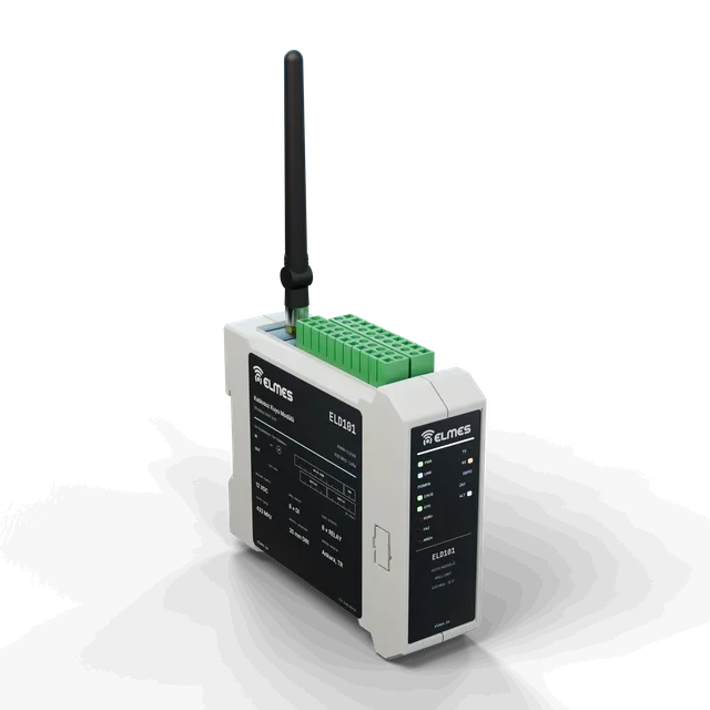
Wireless Well-Tank Control System
No cable needed between pump and tank.
View details: Wireless Well-Tank Control System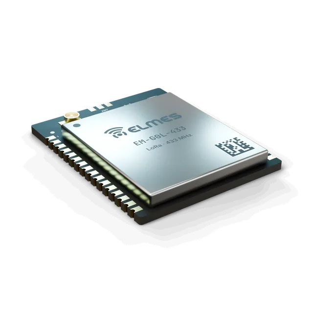 Coming soonModules, Boards & Gateways
STM32 + SX1268 LoRa Module (EM-G0L-433)
A field-proven LoRa path in a castellated module.
View details: STM32 + SX1268 LoRa Module (EM-G0L-433)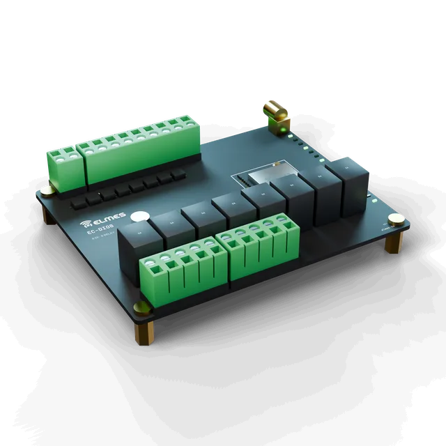 Coming soonModules, Boards & Gateways
I/O Carrier Boards (EC)
Plug in the module, wire the terminals — your wireless I/O box is ready.
View details: I/O Carrier Boards (EC)