Modules, Boards & Gateways · Hardware
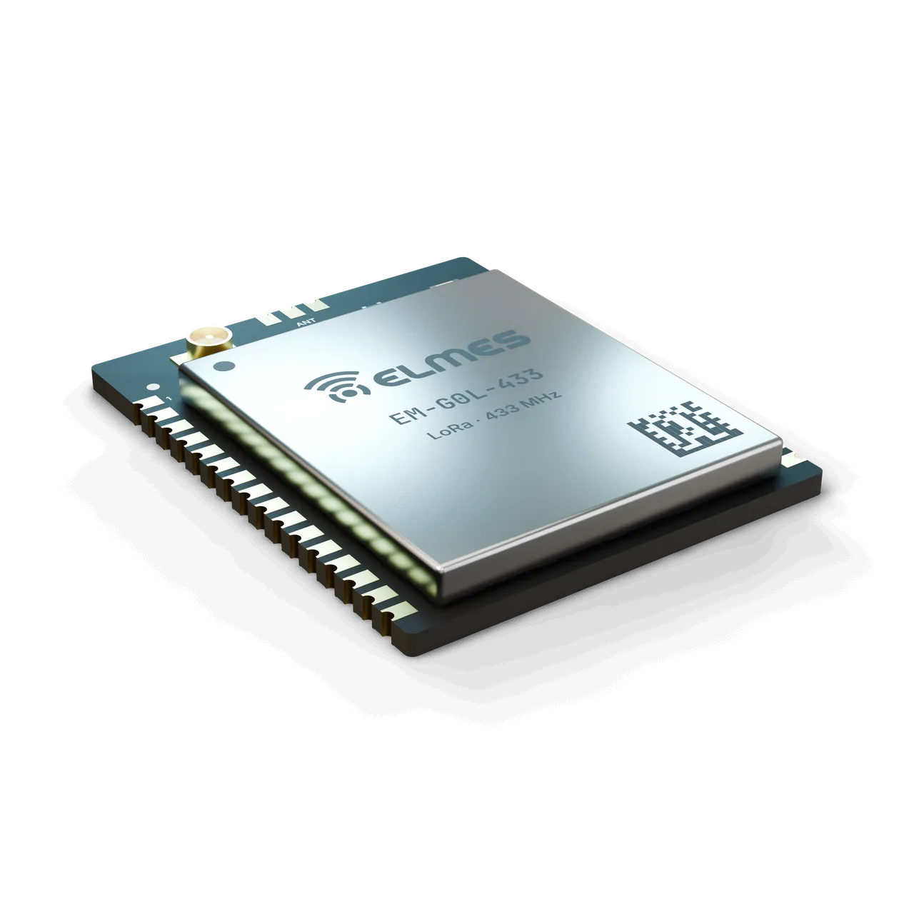
STM32 + SX1268 LoRa Module (EM-G0L-433)
A field-proven LoRa path in a castellated module.
Overview
The problem. A manufacturer that wants to add wireless features faces RF design risk, a RED/EMC documentation burden that repeats for every product, and imported modules with closed firmware. For long-range, low-data-rate industrial control and telemetry at 433 MHz, neither a Wi-Fi module nor 2.4 GHz solutions are enough; LoRa is the right physical layer for getting through walls and terrain and for battery-powered nodes.
The solution. EM-G0L-433 combines an STM32G0 (Cortex-M0+) and an SX1268 in a single castellated module; the matching network, TCXO and PA path come measured by Elmes. The integrator only writes the carrier board and the application code. Variants of the same PCB (battery-powered LP, low-cost K, 868/915 MHz) are managed with a single validation and a single BOM family.
The difference. Off-the-shelf imported LoRa modules either have no MCU (radio only) or a closed one; on EM-G0L-433 the MCU is open and programmed with the SDK. Shared features such as the bootloader, OTA, ID programming and low-power profiles are described on the EM Module Series page.
This product is in development or field testing. Contact us for technical information, pilot use and a preliminary quotation.
Features
- Pin-compatible variants: battery-powered node (EM-G0L-433-LP), low-cost LLCC68 (EM-G0K-433) and SX1262-based 868/915 MHz (EM-G0L-868 / -915); all on the same PCB.
- USB-DFU and CAN-FD: USB-DFU bootloader on the G0B1 version; CAN-FD with a transceiver on the carrier board.
- TCXO-based radio: frequency stability and reliable cold start.
- Telemetry report: RSSI/SNR, battery and temperature data (SDK).
- Open MCU: the application runs directly on the module's STM32; no separate host MCU is needed.
- Shared across the series: bootloader + OTA, ID/channel programming and low-power profiles; details on the EM Module Series page.
Variants
| Model code | MCU | Radio | Power path | USB | Note | Request information |
|---|---|---|---|---|---|---|
| EM-G0L-433 | STM32G071CBT6 (first build) → G0B1CBT6 | SX1268 | Standard LDO | G0B1 version only | Main member | Request information: EM-G0L-433 |
| EM-G0L-433-LP | G071 / G0B1 | SX1268 | Low-Iq LDO, battery measurement | — | Battery-powered node version | Request information: EM-G0L-433-LP |
| EM-G0K-433 | G071 / G0B1 | LLCC68 | Standard | — | Low cost | Request information: EM-G0K-433 |
| EM-G0L-868 / -915 | G071 / G0B1 | SX1262 | Standard | — | 868 / 915 MHz band variant | Request information: EM-G0L-868 / -915 |
Specifications
Values marked “Target” are design targets, next-generation values or chip-vendor data; they are updated as measurement and certification are completed.
| Frequency band | 410–525 MHz (SX1268); Elmes channel plan 433.05–434.79 MHz (ISM) |
|---|---|
| Channels | 8 channels: 433.05–434.79 MHz, 200 kHz spacing, 125 kHz bandwidth |
| Output power | +22 dBm (SX1268 PA); adjustable −9…+22 dBm |
| Receiver sensitivity | −129 dBm @ SF11/BW125; −137 dBm @ SF12 (chip datasheet) |
| Modulation | LoRa (SF5–SF12), (G)FSK |
| Data rate | LoRa 0.018–62.5 kbps; FSK 300 kbps |
| Antenna connection | u.FL and a castellated antenna pin (SMA/pigtail on the carrier); 50 Ω; selected with a 0 Ω jumper or as a build option |
| Open field | ≥ 2000 m (SF9, 2 dBi dipole, 2 m height)Target |
|---|---|
| Industrial / indoor | ≥ 300 mTarget |
| Encryption | AES-128-CCMTarget |
|---|---|
| Addressing and pairing | NetID + 16-bit address; pairing by UID |
| Systems on the same site | ≥ 8 independent networks (channel × NetID)Target |
| Command latency | < 100 ms (SF7, short packet)Target |
|---|---|
| Fail-safe on link loss | Application-defined; SDK timeout 1–60 s |
| Supply | 3.0–3.6 V (module); 9–36 VDC on the carrier |
|---|---|
| Consumption TX / RX | ~118 mA @ 22 dBm / ~5 mA |
| Sleep current | < 10 µA (EM-G0L-433-LP)Target |
| MCU | STM32G071CBT6 → G0B1CBT6; 64 MHz Cortex-M0+, 128 KB flash (G0B1CET6: 512 KB variant) |
|---|
| Exposed pins (minimum) | SWD, 2× UART, 1× SPI, 1× I2C, 8× GPIO, 2× ADC inputs, USB (G0B1), NRST, BOOT0 |
|---|
| Pad count / pitch | 2× 16 castellated pads, 1.27 mm |
|---|---|
| Dimensions | ≤ 20 × 25 mm |
| Mounting | Castellated SMD; keep-out area on the antenna side |
| Operating / storage temperature | −40…+85 °C / −40…+105 °CTarget |
| Humidity | 5–95 %, non-condensing |
| Warranty | 2 yearsTarget |
|---|---|
| Spare-parts support | 5 years |
| Production | Ankara |
Applications
- Wireless digital I/O
- Well, tank and pump control
- Irrigation nodes
- Analog/digital data transfer
- Wireless RS485 / Modbus
- Call and remote-control systems
- Meter reading and telemetry
- Machine control and monitoring
- Security systems
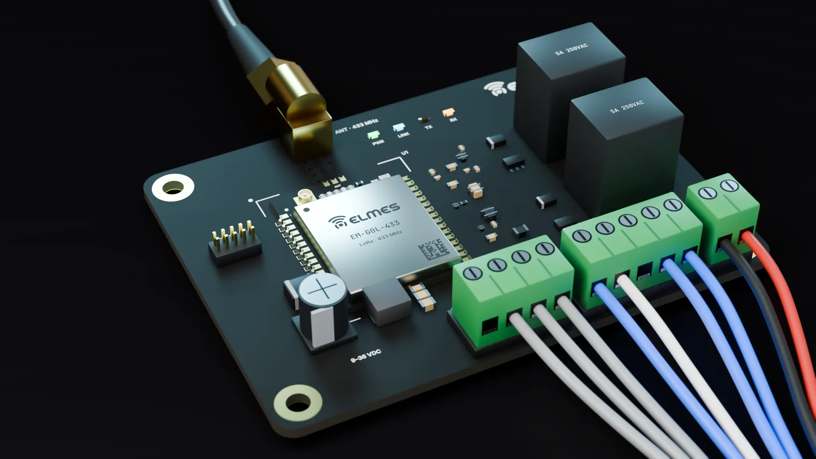
In Elmes products. The module was designed as the core of the following Elmes products: Wireless Digital I/O Link (with the EC-DIO8 carrier), Wireless Well & Tank Control, Wireless Analog & Digital Data Transmitter (EC-AIO / EC-485 / EC-PLS), the central unit of Wireless Waiter Call, the receiver of Wireless Guard Tour Control, Wireless Irrigation Control nodes, the receiver of Wireless Taxi Call and the Wireless RS485 Modem (EC-485). The battery-powered EM-G0L-433-LP version is used in WR-001, Wireless Call Button and Wireless Meter Reading nodes. The same SX1268 LoRa radio path runs in Elmes well and tank control (ELD100) and Firesens fire alarm products in the field.
External OEM. Machine builders adding wireless control or monitoring, agricultural and water automation integrators, meter reading and telemetry companies, and security system manufacturers. Carrier options are on the I/O Carrier Boards page.
Compliance & documentation
EM-G0L-433 is the first module in the family to be certified. In the first phase it is supplied with the note “OEM integrator responsibility”; no module-level certificate has been issued yet.
- Out of scopeEnd-product CE/RED conformityOEM integrator responsibility in the first phase
- TargetIn-house pre-compliance measurement (output power, harmonics, bandwidth, spurious emissions)Internal test report
- TargetCE – RED 2014/53/EU: EN 300 220-2 (radio), EN 301 489-1/-3 (EMC)At an accredited lab; first in line in the family
- TargetRoHS declaration
- TargetCE declaration of conformity (DoC) templateWith the fixture and SDK package
- TargetEM-G0L-868 / -915: separate EN 300 220 testing
Frequently asked questions
Is it software-compatible with MOD-M0?
Yes, it uses the same SDK and radio driver; the footprint differs: MOD-M0 uses a pin header, EM-G0L-433 is castellated.
Does it have USB?
Only on the G0B1 version. The G071 version has no USB; the bootloader works over UART/SWD.
How many channels and networks?
8 channels (433.05–434.79 MHz) × NetID. At least 8 independent networks on the same site are targeted; the figure will be confirmed by measurement.
What is the range?
Measurements are in progress; the target is at least 2000 m in open field (SF9, 2 dBi dipole, 2 m height). In Elmes's previous-generation products, installed devices run reliably at 10 km, and a line-of-sight field test reached 35 km (J-pole antenna, +20 dBm, 2.4 kbaud).
Can I use it in a battery-powered device?
Yes, with the EM-G0L-433-LP version: STOP mode, battery measurement and wake-up inputs.
Is 868 MHz available?
Yes, as the SX1262-based EM-G0L-868 / -915 on the same PCB; the ETSI duty-cycle rules are implemented in the SDK.
Is there a lower-cost version?
EM-G0K-433 (LLCC68): same pinout, no SF12.
Can I use only the radio with my own MCU?
The radio-only EM-NL-433 module is designed for that.
Is it CE certified?
Certification is being done in phases, and EM-G0L-433 is the first member of the family in line. For now it is supplied under OEM integrator responsibility.
Get information about this product
Our engineering team replies within 24 hours.
Related products
 Coming soonModules, Boards & Gateways
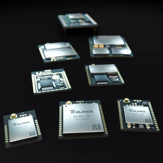
Elmes EM Module Series
One pinout, one SDK — LoRa, Wi-Fi and cellular in a single module family.
6 members
View details: Elmes EM Module Series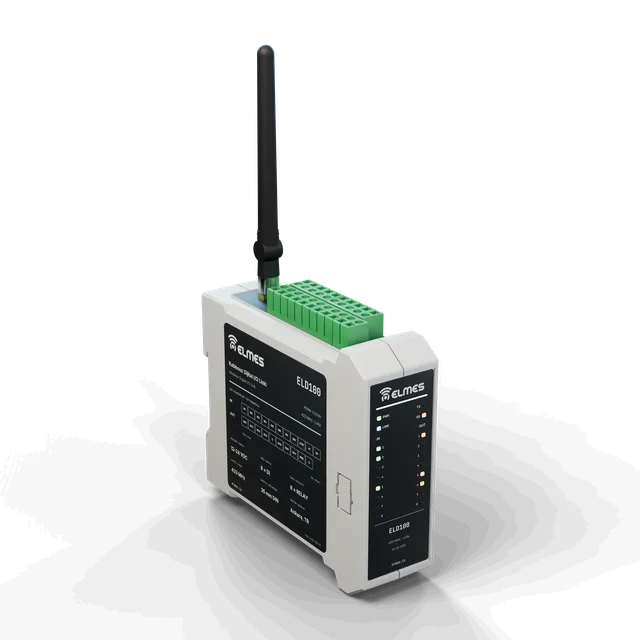 RF & Wireless Systems
Wireless Digital I/O Link — 8 Channels
8 relays, 8 inputs — replace the cable with RF.
View details: Wireless Digital I/O Link — 8 Channels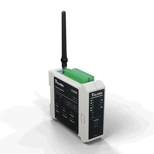 RF & Wireless Systems
Wireless Well-Tank Control System
No cable needed between pump and tank.
View details: Wireless Well-Tank Control System