Modules, Boards & Gateways · Hardware
I/O Carrier Boards (EC)
Plug in the module, wire the terminals — your wireless I/O box is ready.
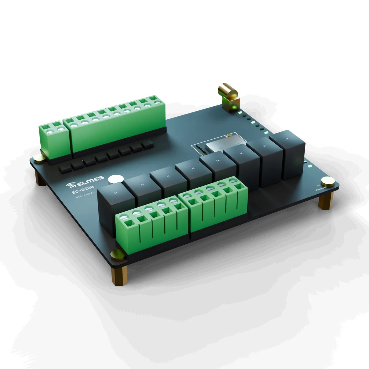
Overview
The problem. In a wireless control project, the module is the small part of the job; most of the time goes into relays, opto-isolated inputs, 4–20 mA measurement, RS485 isolation, 24 V supply protection, terminal layout and the enclosure. In Elmes's existing products (Wireless Well & Tank Control System, Wireless Analog & Digital Data Transmitter, Wireless RS485 Modem), these blocks were redrawn on a separate PCB for every product; an external customer who buys a module has to do the same work from scratch and fights EMC, relay and power-supply problems in the first prototype.
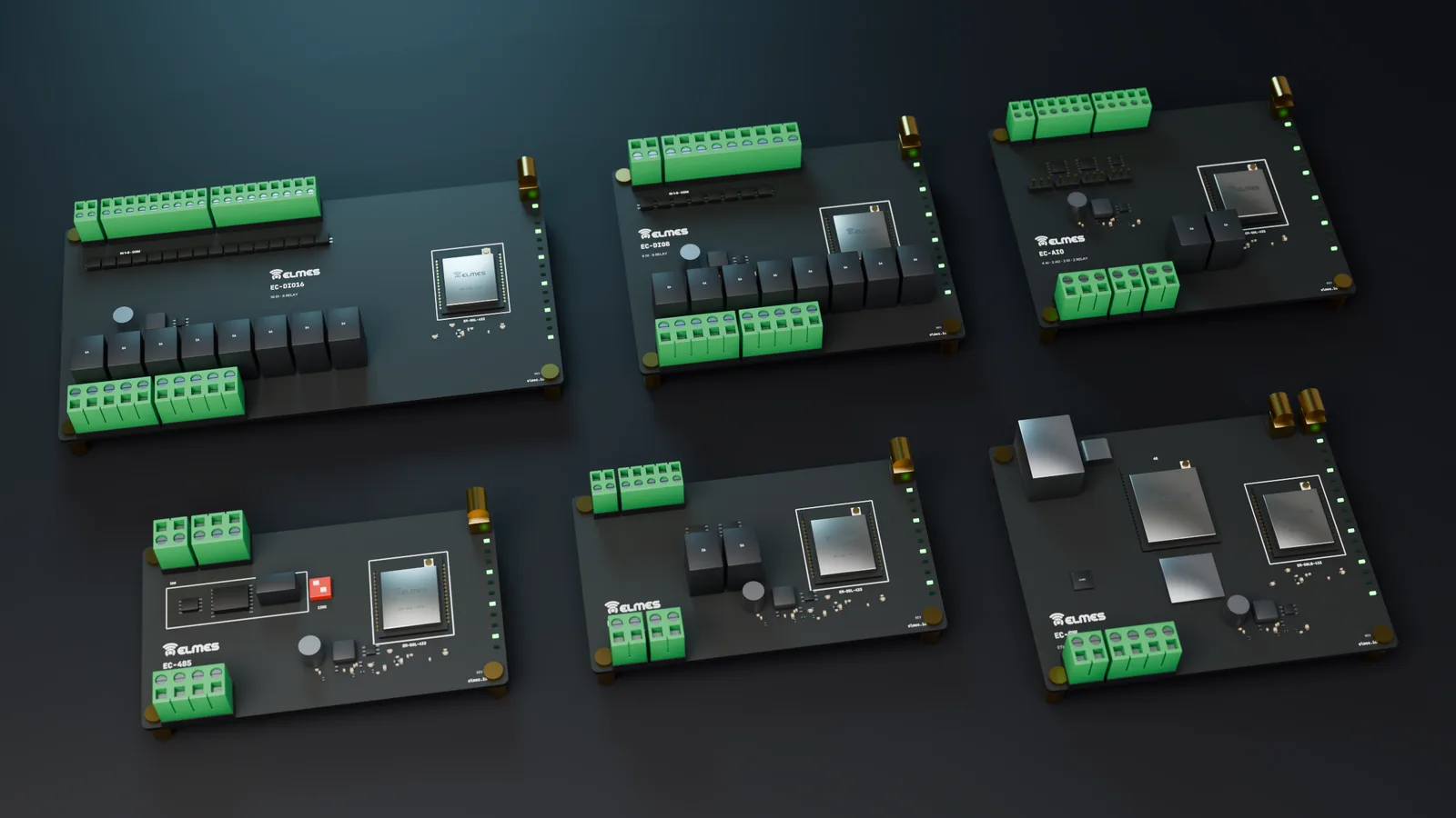
The solution. The EC series separates the function circuitry from the module: the module carries the radio and MCU, the carrier board handles the field side. Five function boards (digital, analog, serial, pulse, gateway) and one wide digital board share the same module socket and the same common block (power, service connector, antenna path, LEDs). Elmes products — well/tank control, data transmitter, RS485 modem, Wireless Gateway / RTU, Wireless Digital I/O Link — 8 Channels and Wireless Meter Reading Node — are these boards loaded with application firmware; external customers use the same board with their own firmware or with Elmes's standard Modbus/I/O firmware.
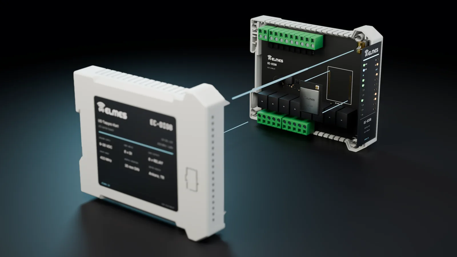
Module and housing. The castellated members of the Elmes Module Series plug into the boards; for applications that need LoRa and Wi-Fi together, the EM-G0LW-433. Two housing options are available: a fast, economical DIN-rail housing or an industrial DIN-rail housing, with the same PCB in both.
This product is in development or field testing. Contact us for technical information, pilot use and a preliminary quotation.
Features
- One footprint: every castellated EM module fits every EC board (LoRa, Wi-Fi, LoRa + Wi-Fi, cellular, no radio).
- Antenna path choice: u.FL pigtail, or on-board SMA via the antenna pin.
- Service connector: SWD + UART for the programming/test fixture and field updates.
- Two housing options: economical and industrial DIN-rail housings, same PCB.
- Fail-safe table: per-relay timeout behavior (release / hold / last state).
- EC-GW: one or more of USB, Ethernet and 4G depending on the build; the Wireless Gateway / RTU is built on this board.
- TargetAutomatic board detection: an ID resistor lets the same firmware pick the I/O map for the board type.
- TargetStandard I/O firmware profile: wireless I/O mirroring (point-to-point), Modbus RTU slave (wired) and gateway mode; product firmware builds on top of it.
- TargetEC-PLS non-volatile counters: counter values kept in non-volatile memory; nothing lost on power failure.
Board family
| Model code | Function | I/O | Housing (planned) | Related Elmes products | Request information |
|---|---|---|---|---|---|
| EC-DIO8 | Digital I/O | 8 × opto DI (12–24 V), 8 × relay NO/NC 5 A | 6-module DIN rail | Well/tank control, data transmitter, digital I/O link | Request information: EC-DIO8 |
| EC-DIO16 | Wide digital I/O | 16 × opto DI, 8 × relay (or 16 × transistor) | 9-module DIN rail | Data transmitter (RT152-M16) | Request information: EC-DIO16 |
| EC-AIO | Analog | 4 × 4–20 mA / 0–10 V input (16-bit), 2 × 4–20 mA / 0–10 V output, 2 × DI, 2 × relay | 6-module DIN rail | Analog data transmitter | Request information: EC-AIO |
| EC-485 | Serial bridge | 1 × isolated RS485 (Modbus RTU), 1 × RS232 (optional), 2 × DI, 2 × DO | 2-module DIN rail | RS485 modem (EL485L-S), gateway / RTU | Request information: EC-485 |
| EC-PLS | Pulse / counter | 4 × pulse input (S0/reed, 10 kHz), 2 × relay | 2-module DIN rail | Data transmitter, meter reading | Request information: EC-PLS |
| EC-GW | Gateway | Ethernet (optional), USB, 4G modem slot (EM-G0C), 2 × DI/DO | 6-module DIN rail | Gateway / RTU | Request information: EC-GW |
Specifications
Values marked “Target” are design targets, next-generation values or chip-vendor data; they are updated as measurement and certification are completed.
| RF characteristics | Set by the fitted EM module (e.g. EM-G0L-433); the board does not affect RF |
|---|---|
| Antenna connector | On-board female SMA (antenna pin path) or u.FL pigtail → panel SMA; 50 Ω |
| Range | Module value; when housed, the antenna is mounted outside via SMA |
| Identity / encryption | Provided by the module; board type identified by an ID resistor |
| Input → wireless → relay latency | < 150 ms (SF7; input filter 10 ms + RF < 100 ms + relay 10 ms)Target |
|---|---|
| Fail-safe on communication loss | 1–60 s adjustable; default: relays release |
| Supply | 9–36 VDC; reverse-polarity diode, TVS, PTC fuse |
|---|---|
| Idle consumption | < 30 mA @ 24 V (module included, RX)Target |
| Relay coil current | ~70 mA per relay @ 12 V coil |
| 5 V coil relay option | ~40 mA per relayTarget |
| EC-GW peak current | 2 A class with modem @ 5 V |
| Digital input | Opto-isolated, 12–24 V, ~3 mA, 10 ms software filter |
|---|---|
| Input grouping | Common GND or isolated groupTarget |
| Relay | 5 A / 250 VAC, NO/NC (SPDT), coil varistor/diode, LED |
| Transistor output (EC-DIO16 option) | Open-drain, 0.5 A, 30 V, protected |
| Analog input (EC-AIO) | 4 × 16-bit (ADS1115 class), 4–20 mA (250 Ω) / 0–10 V selectable by jumper |
| Analog input accuracy | ±0.1 % FSTarget |
| Analog output (EC-AIO) | 2 × 12-bit (MCU DAC or external) + 4–20 mA driver / 0–10 V |
| Analog output accuracy | ±0.2 % FSTarget |
| Pulse input (EC-PLS) | 4 × S0 (DIN 43864) / reed / open-collector; 10 kHz max.; adjustable debounce; 32-bit counter |
| RS485 (EC-485) | Isolated, 9.6–115.2 kbps, Modbus RTU, 120 Ω termination switch, bias |
|---|---|
| RS232 (EC-485, optional) | 3-wire, 115.2 kbps |
| Gateway (EC-GW) | USB-CDC, Ethernet (optional, SPI Ethernet IC), 4G modem slot (EM-G0C), 2 × DI/DO |
| USB-CDC implementation | On the module MCU or via a bridge ICTarget |
| Service connector | SWD + UART, 6-pin 1.27 mm (shared with the fixture) |
| Housing | Economical or industrial DIN-rail housing; width 2 / 6 / 9 modules (36 / 108 / 162 mm, 1 module = 18 mm)Target |
|---|---|
| Mounting | 35 mm DIN rail (EN 60715) |
| Terminals | Pluggable, 5.08 mm, 2.5 mm² |
| Ingress protection | IP20 (inside a cabinet) |
| Operating / storage temperature | −25…+70 °C (relay/terminal limit) / −40…+85 °C |
| Humidity | 5–95 %, non-condensing |
| Warranty | 2 yearsTarget |
|---|---|
| Spare-parts support | 5 years |
| Manufacturing | Ankara |
Applications
- Pump and float control
- Wireless digital I/O links
- Machine and door/barrier receivers
- Analog telemetry nodes
- Wireless PLC I/O expansion
- Water and electricity meter reading
- Gateways and RTUs
- Panel builders and integrators
| Board | Elmes product / application |
|---|---|
| EC-DIO8 | Wireless Well & Tank Control System (pump/float), Wireless Digital I/O Link — 8 Channels, Wireless Machine Start & Control receiver, Smart Door Control & Access door/barrier receiver, Wireless Irrigation Control System valve node |
| EC-DIO16 | RT152 refresh for the Wireless Analog & Digital Data Transmitter, Wireless Crane Control System receiver (split architecture) |
| EC-AIO | Analog transfer, level/pressure/flow telemetry node, joystick/potentiometer link |
| EC-485 | Wireless RS485 Modem, wireless PLC I/O expansion, serial end of the Gateway/RTU |
| EC-PLS | Wireless Meter Reading Node (water/electricity S0), production counter |
| EC-GW | Wireless Gateway / RTU (USB/Ethernet/4G), Firesens gateway, Telemetry & Process Intelligence cloud end |
External OEM use: panel builders and integrators, water utilities, agriculture and building automation.
Compliance & documentation
There is no documentation for the EC boards yet. The CE declaration of conformity is prepared at product level, together with the RED status of the fitted module. The EC-DIO8 + EM-G0L combination (Wireless Digital I/O Link — 8 Channels) is documented first; the other boards are derived from the same common block.
- TargetEMC — EN 61000-6-2 / EN 61000-6-4 (industrial environment) or EN 61326-1
- TargetLVD — EN 61010-1 (relay contacts 250 VAC)
- TargetRoHS / REACH declaration
- TargetCE declaration of conformity (together with the RED status of the fitted module)
Frequently asked questions
Which modules can be fitted?
Does the module come soldered on?
Your choice: board and module soldered and tested, or the board on its own.
How does it communicate with a PLC?
Modbus RTU with EC-485; Modbus TCP/MQTT with EC-GW (Wireless Gateway / RTU). DIO boards connect directly to PLC inputs through dry contacts.
What happens to the relays if communication is lost?
It is defined per relay in the board profile: release (default), hold or last state; timeout 1–60 s.
Can the antenna stay inside the cabinet?
In a plastic cabinet and over short distances, yes; in a metal cabinet, an external SMA antenna via a pigtail is required (Industrial RF Antenna Series).
Which housing is used?
The economical option uses a locally made, quickly available DIN-rail housing; the industrial option uses a premium DIN-rail housing. The PCB is the same in both.
How many points can one board control?
EC-DIO8: 8 inputs + 8 relays. To expand, a second board is added to the RS485 chain or on a wireless address.
Can I write my own firmware?
Yes. EM-SDK Open (Apache-2.0) comes with EC I/O profile examples; board detection and the I/O map are part of the SDK (Module Programming/Test Fixture + SDK Package).
Get information about this product
Our engineering team replies within 24 hours.
Related products
 Coming soonModules, Boards & Gateways
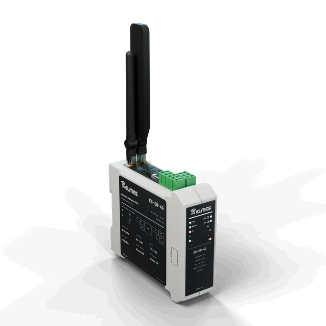
Wireless Gateway / RTU
Connect every LoRa node in the field to SCADA, the cloud and PLCs with a single box.
View details: Wireless Gateway / RTU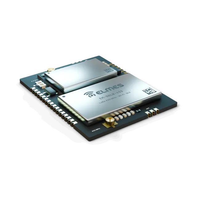 Coming soonModules, Boards & Gateways
STM32 + SX1268 + ESP32 Module (EM-G0LW-433)
LoRa on the field side, Wi-Fi on the central side — a gateway core in one module.
View details: STM32 + SX1268 + ESP32 Module (EM-G0LW-433)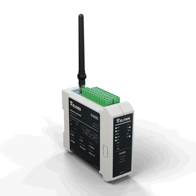 RF & Wireless Systems
Wireless Well-Tank Control System
No cable needed between pump and tank.
View details: Wireless Well-Tank Control System