Modules, Boards & Gateways · Hardware
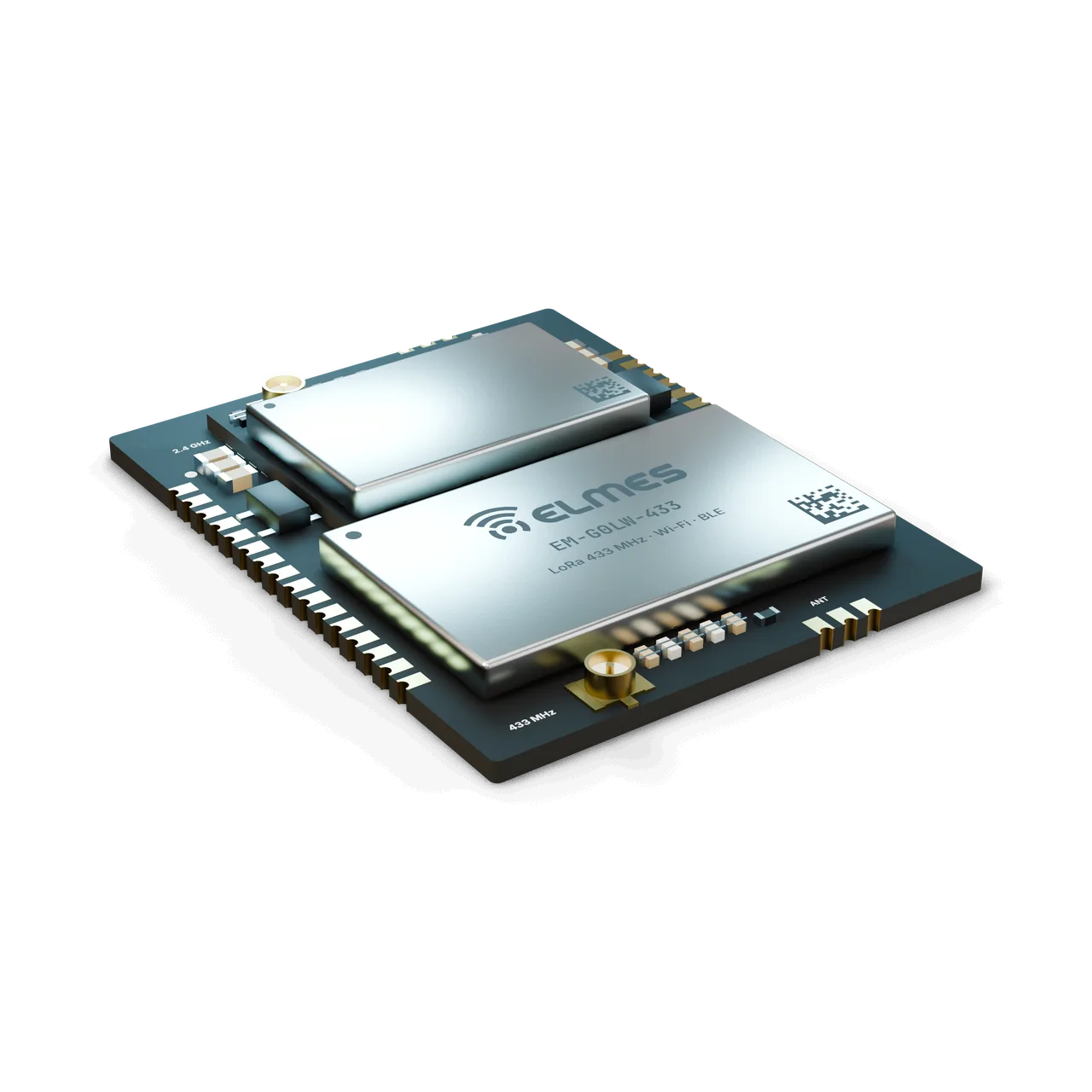
STM32 + SX1268 + ESP32 Module (EM-G0LW-433)
LoRa on the field side, Wi-Fi on the central side — a gateway core in one module.
Overview
The problem. Every Elmes RF system has a “central end”: the fire alarm gateway, the irrigation master, the taxi call receiver, the well and tank receiver. Until now these were built with separate boards, different MCUs and different connection paths (USB-CDC, Raspberry Pi, GSM–CAN). For every new product the LoRa radio, connectivity and power were designed again, and placing Wi-Fi and LoRa on the same board caused coexistence problems each time.
The solution. EM-G0LW-433 standardizes this central end in a single module. The STM32G0 manages the LoRa network (addressing, ACK, timing, local I/O and RTU logic); the ESP32 is only a Wi-Fi/BLE “modem” and uses the same bridge protocol as EM-G0W: data to the Telemetry & Process Intelligence platform over MQTT/HTTP, maintenance through a local web interface, and phone access over BLE. USB (G0B1) keeps PC-side gateway use available. Ethernet and a 4G modem are added on the carrier board (EC-GW carrier, EM-G0C cellular module).
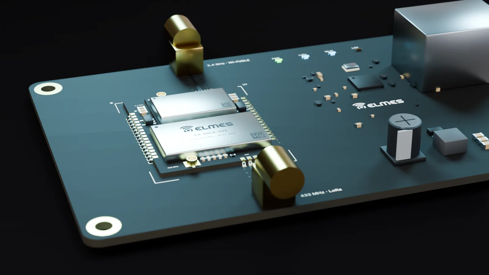
RF coexistence is solved once, at module level: separate antennas, a harmonic filter on the 433 MHz PA output, separate power domains and timing in the SDK (planned: deferring Wi-Fi transmission during the LoRa receive window). The module's main user is the Wireless Gateway / RTU product.
This product is in development or field testing. Contact us for technical information, pilot use and a preliminary quotation.
Features
- Dual radio, single SDK: the LoRa network manager role (NetID, address table, ACK, repeater profile — Pro layer) and the ESP bridge protocol in the same application.
- Gateway modes: USB-CDC bridge (PC application), MQTT/HTTP, Modbus RTU/TCP (via the EC-485 or Ethernet carrier), local RTU logic.
- OTA distributor: the gateway broadcasts OTA updates to the nodes over LoRa and receives its own image over Wi-Fi/USB.
- RF coexistence measures: separate antennas, a low-pass filter (LPF), separate LDOs and timing in the SDK.
- CAN-FD (G0B1): with a transceiver on the carrier; continues the GSM–CAN gateway applications.
- Pin-compatible 868/915 MHz version: SX1262-based EM-G0LW-868 / -915 on the same PCB.
- Shared across the series: bootloader, ID programming and telemetry; details on the EM Module Series page.
- TargetEdge AI: local analytics on the gateway; may require an STM32H7-class MCU.
- TargetLocal maintenance interface: node list, RSSI/SNR map, channel plan and OTA distribution over Wi-Fi AP/BLE.
- TargetLow-cost version: LLCC68-based EM-G0KW-433, on demand.
Variants
| Model code | MCU | LoRa | ESP module | USB | Note | Request information |
|---|---|---|---|---|---|---|
| EM-G0LW-433 | STM32G0B1CBT6 (gateway requiring USB); G071 only in USB-less prototypes | SX1268 | Same ESP32 MINI module as EM-G0W | G0B1 | Main member | Request information: EM-G0LW-433 |
| EM-G0LW-868 / -915 | G0B1 | SX1262 | Same | G0B1 | 868 / 915 MHz band variant | Request information: EM-G0LW-868 / -915 |
| EM-G0KW-433Target | G0B1 / G071 | LLCC68 | Same | — | Low-cost central unit; on demand | Request information: EM-G0KW-433 |
Specifications
Values marked “Target” are design targets, next-generation values or chip-vendor data; they are updated as measurement and certification are completed.
| Frequency band | 410–525 MHz (SX1268); Elmes channel plan 433.05–434.79 MHz |
|---|---|
| Channels | 8 (same as EM-G0L-433): 200 kHz spacing, 125 kHz bandwidth |
| Output power | +22 dBm (SX1268 PA), adjustable −9…+22 dBm |
| Receiver sensitivity | −129 dBm @ SF11/BW125 (chip datasheet) |
| Sensitivity loss during Wi-Fi TX | ≤ 1 dBTarget |
| Modulation / data rate | LoRa SF5–SF12, (G)FSK; LoRa 0.018–62.5 kbps |
| Frequency band | 2400–2483.5 MHz; 802.11 b/g/n, BLE 5 |
|---|---|
| Output power / sensitivity | ≈ +20 dBm class / ≈ −97 dBm @ 11b (Espressif datasheet) |
| Antenna connection | u.FL + antenna pin (2.4 GHz), 50 Ω; separate from the LoRa antenna |
| Antenna placement | Antennas on opposite edges; LPF on the 433 MHz PA output |
|---|---|
| Antenna spacing / isolation | ≥ 15 mm / ≥ 30 dB @ 2.4 GHzTarget |
| LoRa open field / indoor | ≥ 2000 m (SF9, 2 dBi dipole, 2 m height) / ≥ 300 m — same as EM-G0L-433Target |
|---|---|
| Wi-Fi indoor (to AP) | ≥ 30 mTarget |
| Encryption | LoRa: AES-128-CCM; MQTT: TLS 1.2Target |
|---|---|
| Addressing / Wi-Fi security | LoRa: NetID + 16-bit address + UID; Wi-Fi: WPA2/WPA3 |
| Systems on the same site | ≥ 8 independent LoRa networks (channel × NetID)Target |
| Managed nodes | Address space 65,536; ≥ 256 nodes @ 1 report per minuteTarget |
| Command latency | LoRa end-to-end < 100 ms (SF7); LoRa → MQTT < 200 ms (local network)Target |
|---|---|
| Fail-safe on link loss | Node timeout 1–60 s (SDK) |
| On Wi-Fi loss | Local operation continues, data is bufferedTarget |
| Supply | 3.0–3.6 V (module); 9–36 VDC on the EC-GW carrier; separate LDOs for MCU/LoRa and ESP |
|---|---|
| Consumption | LoRa TX ~118 mA @ 22 dBm; Wi-Fi TX peak ≈ 350 mA (approximate); no sleep mode foreseen |
| MCU | STM32G0B1 (USB-FS, CAN-FD); 128 KB (CBT6) or 512 KB (CET6) flash; G071 only in USB-less prototypes |
|---|---|
| Internal connections | SPI1 ↔ SX1268 (DIO1/DIO2/BUSY/RST); UART ↔ ESP (RTS/CTS, ESP_EN, ESP_IO0, HOST_INT) |
| Exposed pins (minimum) | Series-wide layout: SWD, 2× UART, 1× SPI, 1× I2C, 8× GPIO, 2× ADC, USB, NRST, BOOT0 |
|---|---|
| CAN-FD | TX/RX (G0B1), shared with GPIOTarget |
| Pad count / pitch | 2× 16 castellated, 1.27 mm (series-wide) |
|---|---|
| Dimensions | ≤ 20 × 25 mm (series-wide); 25 × 32 mm if it does not fit, with the pad layout retainedTarget |
| Mounting | Castellated SMD; keep-out areas on both antenna sides |
| Operating / storage temperature | −40…+85 °C / −40…+105 °CTarget |
| Humidity | 5–95 %, non-condensing |
| Warranty | 2 yearsTarget |
|---|---|
| Spare-parts support | 5 years |
| Production | Ankara |
Applications
- LoRa gateway / RTU
- Fire alarm gateway
- Irrigation master
- Well and tank receiver
- Taxi call receiver
- LoRa → MQTT bridge
- IIoT retrofit
- Telemetry data collection
In Elmes products. The main core across all layers of the Wireless Gateway / RTU product; the successor of the Firesens USB gateway (bridge to the map HMI and the PC application); the Wireless Irrigation Control master, the Wireless Well & Tank Control receiver (central side) and the Wireless Taxi Call receiver/display unit; a component of the IIoT Retrofit Kit and a data source for Telemetry & Process Intelligence.
External OEM. Integrators that want a LoRa field network with a Wi-Fi/MQTT central end. When the module is sold as the Wireless Gateway / RTU product, the product-level declaration of conformity is issued for that product.
Compliance & documentation
In the first phase it is supplied with the note “OEM integrator responsibility”; no module-level certificate has been issued yet. The module requires testing in two bands (433 MHz and 2.4 GHz). When sold as the Wireless Gateway / RTU product, the product-level declaration of conformity is issued for that product.
- Out of scopeEnd-product CE/RED conformityOEM integrator responsibility in the first phase
- TargetEN 300 220-2 (433 MHz radio)Derivation from the EM-G0L-433 / EM-NL-433 test results depends on the accredited lab's opinion
- TargetEN 300 328 (2.4 GHz radio)Using a modular-approved ESP32 module
- TargetEN 301 489-1/-3/-17 (EMC, complete module)
- TargetEN 62368-1 (in product context, with the EC-GW carrier)
- TargetESP32 module manufacturer documentation (modular approval)Manufacturer's declaration; to be collected and verified during procurement
- TargetEM-G0LW-868 / -915: separate EN 300 220 testing
- TargetRoHS / REACH declaration
Frequently asked questions
Why one module instead of two (EM-G0L + EM-G0W)?
A single carrier slot, a single SDK application and RF coexistence solved inside the module; cost and board area go down.
Can it work as a gateway without Wi-Fi?
Yes: over USB (G0B1) or through the EC-485/Ethernet carrier; Wi-Fi/BLE can be turned off. For a USB-only gateway, EM-G0L-433 may also be sufficient.
How many nodes can it manage at once?
The address space is 65,536; the practical number depends on channel, SF and report rate. At least 256 nodes at 1 report per minute are targeted, and a calculator is planned for the SDK.
Do Wi-Fi and LoRa interfere with each other?
It is a design topic: with separate antennas, filtering and timing, the target is at most 1 dB of LoRa sensitivity loss. The measured result will be added to the specifications table.
Does it support 4G or Ethernet?
Not on the module itself; the EC-GW carrier offers an Ethernet option and a slot for the cellular module (EM-G0C).
I have a Raspberry Pi gateway; how do I migrate?
The same MQTT/CSV data format is targeted (Wireless Gateway / RTU); the PC application keeps working over USB-CDC.
Is there an 868 MHz gateway?
Yes, the EM-G0LW-868 version (SX1262); in that case the nodes must also be on 868 MHz.
Does it have CE/RED certification?
In the first phase it is supplied under OEM integrator responsibility; certification for both bands is being done in phases.
Get information about this product
Our engineering team replies within 24 hours.
Related products
 Coming soonModules, Boards & Gateways
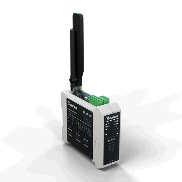
Wireless Gateway / RTU
Connect every LoRa node in the field to SCADA, the cloud and PLCs with a single box.
View details: Wireless Gateway / RTU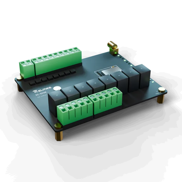 Coming soonModules, Boards & Gateways
I/O Carrier Boards (EC)
Plug in the module, wire the terminals — your wireless I/O box is ready.
View details: I/O Carrier Boards (EC)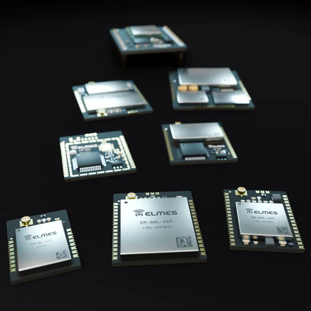 Coming soonModules, Boards & Gateways
Elmes EM Module Series
One pinout, one SDK — LoRa, Wi-Fi and cellular in a single module family.
6 members
View details: Elmes EM Module Series