Modules, Boards & Gateways · Hardware

Elmes EM Module Series

Coming soon

One pinout, one SDK — LoRa, Wi-Fi and cellular in a single module family.

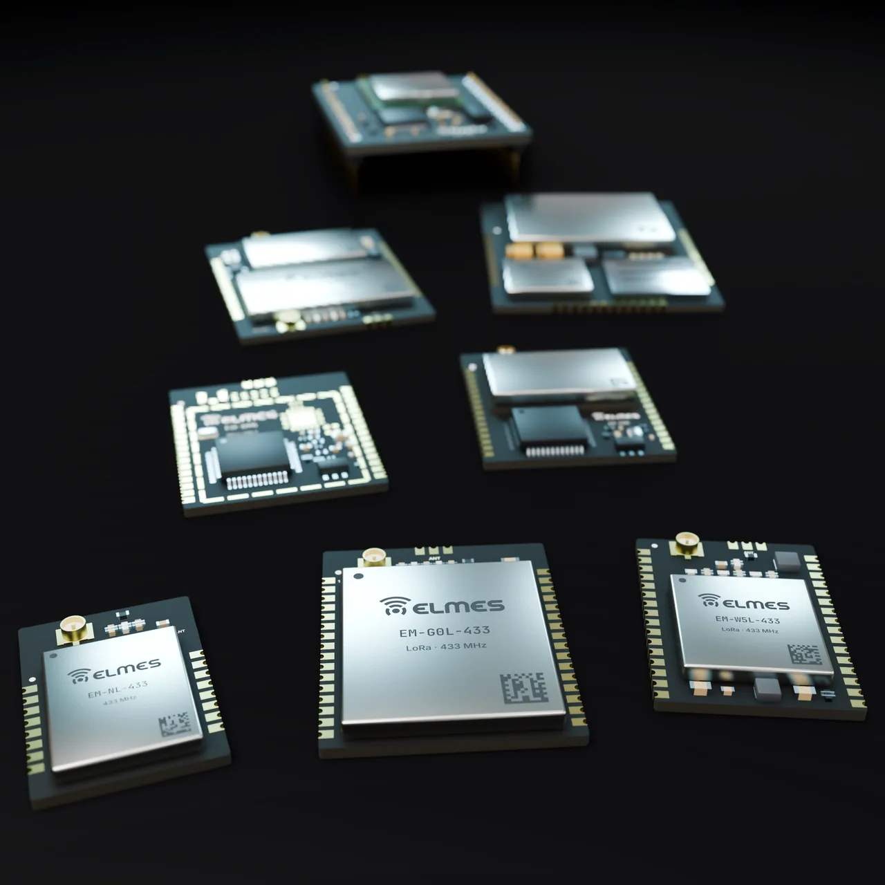
All EM series members on a dark surface: castellated LoRa, Wi-Fi and cellular modules with nickel RF shields

Overview

The problem. When a machine or device manufacturer wants to add wireless features, it runs into three obstacles: (1) RF design and the matching network require expertise, and range and interference problems surface in the first prototype; (2) RED/EMC testing and the documentation burden repeat for every new product; (3) off-the-shelf Far East modules are cheap, but their firmware is closed, their pinout and supply change with the next revision, and there is no local support in Turkish.

The solution. The EM series opens up the MCU + radio module that Elmes uses in its own products: a measured radio path, an open SDK and bootloader, a fixed pinout and a documented production test. The integrator only writes the carrier board and the application code; the radio, power management and update infrastructure are ready. Because the same pinout is shared by the LoRa (L), Wi-Fi/BLE (W), cellular (C) and combined LoRa + Wi-Fi (LW) members, a product family can offer different connectivity options from a single PCB design.

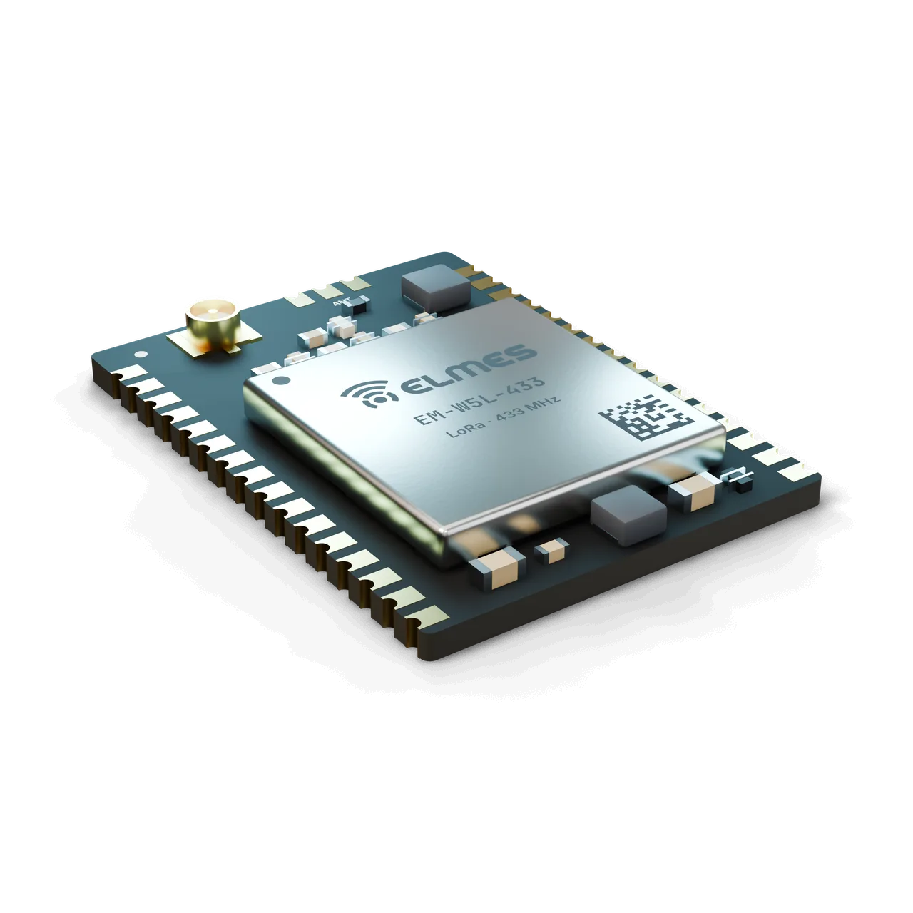
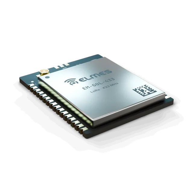
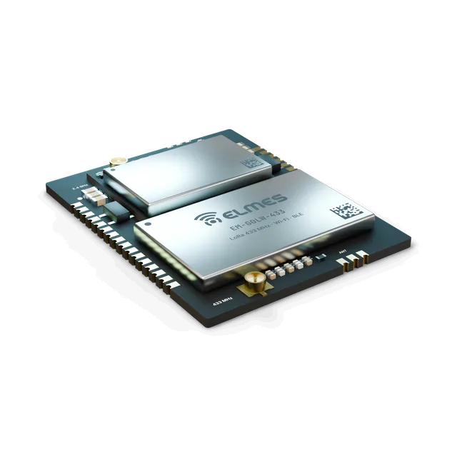
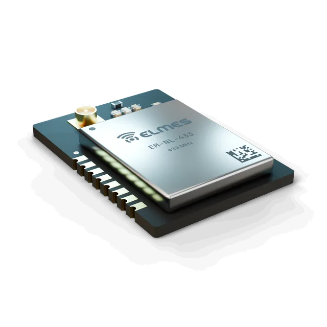
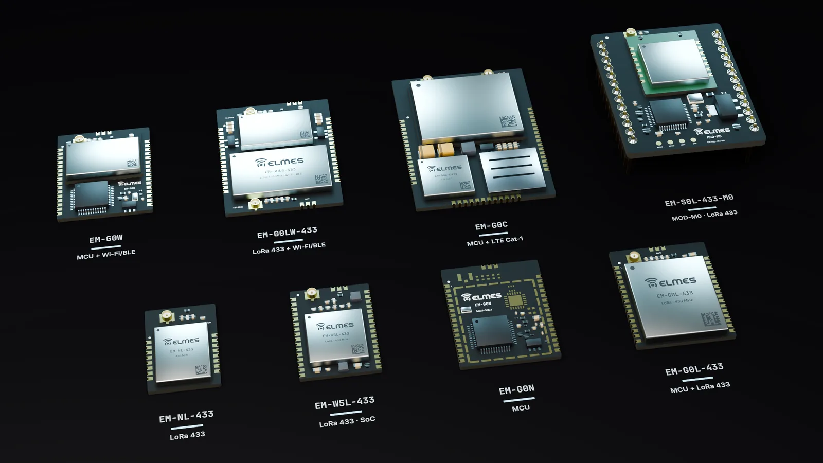
The family. The common MCU is the STM32G0 (Cortex-M0+). EM-G0L-433 is the main MCU + LoRa member; EM-G0LW-433 combines LoRa and Wi-Fi/BLE in a gateway core; EM-NL-433 is a radio-only module for designs that already have their own MCU. EM-G0W is the Wi-Fi/BLE member, EM-G0C the cellular member, EM-G0N the radio-less core and EM-W5L-433 the STM32WLE5 integrated LoRa member. MOD-M0, already in the field, provides a migration path to the new series with the same software.

Ecosystem. The modules are used on I/O carrier boards with relay, analog, RS485 and pulse-counter interfaces; a fixture and SDK package covers programming, production testing and software development.

EM series side by side: EM-NL-433, EM-W5L-433, EM-G0N, EM-G0L-433, EM-G0W, EM-G0LW-433, EM-G0C and MOD-M0
Product family
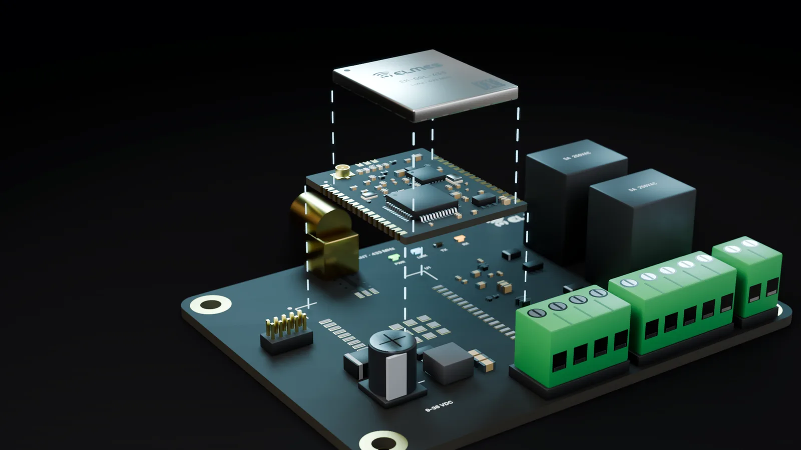
Exploded view: RF shield, EM-G0L-433 module board and the solder-pasted footprint on a carrier board
Exploded view

This product is in development or field testing. Contact us for technical information, pilot use and a preliminary quotation.

Features

  • Bootloader + OTA: updates over UART/USB and LoRa/Wi-Fi; the infrastructure comes from DiscOS and the Elmes well and tank control products.
  • ID and channel programming: ID, channel and calibration data are written in production and can be changed in the field.
  • Low-power profiles: STOP mode, wake-up sources and battery measurement (in the EM-G0L-433-LP version).
  • Telemetry report: RSSI/SNR, battery and temperature; already in use on Firesens fire alarm boards.
  • ESP bridge (W): the STM32 handles real-time control, the ESP32 handles communication only; standard UART protocol.
  • Dual radio (LW): LoRa on the field side + Wi-Fi/BLE for local access and configuration.
  • TargetCommon pinout standard: the same pad layout on every member; the connectivity option changes without changing the carrier board.
  • TargetOpen SDK (Apache-2.0): HAL, radio driver, bootloader, protocol core and examples delivered as source code.

Family members

Family members
Model codeContentsStatusRequest information
EM-S0L-433-M0MOD-M0: STM32F070 + SX1268, legacy pin-header footprintIn the fieldRequest information: EM-S0L-433-M0
EM-G0L-433STM32G0 + SX1268 LoRa, castellatedNewRequest information: EM-G0L-433
EM-G0WSTM32G0 + ESP32 (Wi-Fi/BLE)NewRequest information: EM-G0W
EM-G0LW-433STM32G0 + SX1268 + ESP32 (LoRa + Wi-Fi/BLE gateway core)NewRequest information: EM-G0LW-433
EM-NL-433Radio-only SX1268, SPI interfaceNewRequest information: EM-NL-433
EM-G0K-433 / EM-NK-433Low-cost LLCC68 LoRa (with MCU / radio-only)NewRequest information: EM-G0K-433 / EM-NK-433
EM-G0L-868 / -915, EM-NL-868SX1262 band variants (868 / 915 MHz)NewRequest information: EM-G0L-868 / -915, EM-NL-868
EM-G0NMCU-only core (no radio)NewRequest information: EM-G0N
EC-DIO8 / EC-AIO / EC-485 / EC-PLSI/O carrier boards (digital, analog, RS485, pulse counter)NewRequest information: EC-DIO8 / EC-AIO / EC-485 / EC-PLS
EM-G0CCellular 4G / NB-IoTNewRequest information: EM-G0C
EM-G0L-433-LPBattery-powered LoRa node versionNewRequest information: EM-G0L-433-LP
EM-S7L-433TargetSTM32H7 + LoRaPlannedRequest information: EM-S7L-433
ET-FIX-EM / ET-SDK-EMProgramming/test fixture + SDK packageNewRequest information: ET-FIX-EM / ET-SDK-EM
EM-W5L-433STM32WLE5 integrated MCU + LoRaNewRequest information: EM-W5L-433

Specifications

Values marked “Target” are design targets, next-generation values or chip-vendor data; they are updated as measurement and certification are completed.

Architecture
Common MCUSTM32G0 (Cortex-M0+); G0B1 on a single footprint (USB-FS, CAN-FD; CBT6 128 KB, CET6 512 KB flash); G071 (no USB) for price-critical versions
Connectivity optionsLoRa 433 MHz (SX1268), LoRa 868/915 MHz (SX1262), low-cost LoRa (LLCC68), Wi-Fi/BLE (ESP32), LoRa + Wi-Fi/BLE, cellular 4G/NB-IoT, STM32WLE5 integrated LoRa, radio-less core
Interfaces
PinoutCommon pinout standard across all members; castellated pads in the new seriesTarget
Exposed interfacesSWD, UART, SPI, I2C
Internal layoutRadio SPI1, USB, SWD and ESP-bridge USART placement as on MOD-M0; retained in the new series
Antenna connectoru.FL / SMA
Radio
How RF values are statedEvery RF value in two columns: chip datasheet and Elmes measurement (date, equipment, antenna, distance); range is stated only as measured
Test equipmentSpectrum analyzer, RF power meter, antenna analyzer, SWR meter (in-house at Elmes)
Range
Previous-generation field test35 km — line of sight, J-pole antenna, +20 dBm (100 mW), 2.4 kbaud (CC1101-based generation)
Previous-generation safe rangeInstalled devices operating at 10 km
New seriesAt least equal to the previous generation (SX1268, +22 dBm, LoRa SF9–SF12)Target
Power
Supply3.3 V
Software
UpdatesBootloader; OTA over UART/USB and LoRa/Wi-Fi
ID programmingID, channel and calibration written in production; changeable in the field
Licensing & support
Open SDKApache-2.0: HAL, radio driver, bootloader, protocol core, examplesTarget
Pro layerElmes product application layer, network profiles (repeater/mesh), fleet/OTA server tools and production scripts are licensed separately
SupportTechnical support in Turkish; design and production in Ankara
Mechanical & environmental
MountingCastellated SMD in the new series; pin header on MOD-M0
Operating temperature−40…+85 °CTarget
Warranty & service
Warranty2 yearsTarget
Spare-parts support5 years

Member module details

Series members without a page of their own; all share the same pinout and SDK. Full specifications open under each member.

EM-S0L-433-M0Available

MOD-M0 — STM32 + SX1268 Module (EM-S0L-433-M0)

A LoRa core already in the field — use it today, move to the new series with the same software tomorrow.
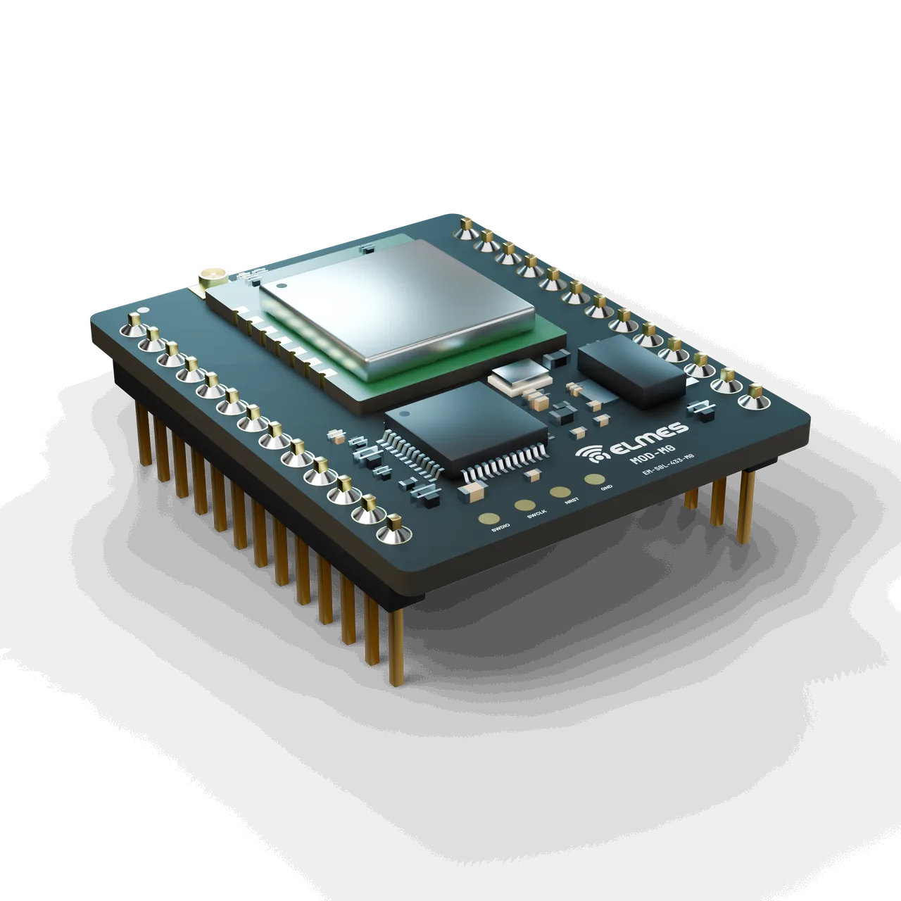
MOD-M0 (EM-S0L-433-M0): pin-header board carrying a ready-made LoRa radio module and u.FL

The problem. Elmes's second-generation LoRa products (well and tank control, fire alarm, call remote) repeated the same MCU + LoRa core on three separate boards; radio layout, programming and production testing had to be set up again for each product. Spare supply and documentation for the old module were scattered.

The solution. MOD-M0 brings this core together in a single pin-header module: STM32F070 + a DRF1268T off-the-shelf LoRa module (SX1268) + USB + SWD. The product board only carries power, I/O and terminals. ID and channel data are written in production with production scripts, and devices in the field are repaired with the same module.

Migration to the new series. Until the new series (EM-G0L-433) arrives, MOD-M0 is the production and service core of these products; after that it stays in production as a spare part and for OEM boards that need a pin header. EM-G0L-433 is recommended for new board designs.

  • Pin-to-pin spare part: plugs directly into well and tank control (ELD100) and Firesens boards in the field; same pinout as the old module.
  • Built-in USB-CDC: programming and service through the F070's USB-FS; the Firesens USB gateway uses this path. In the new series, USB is available only on the G0B1 version.
  • Off-the-shelf radio module (DRF1268T): with TCXO and its own matching network; Elmes carries no RF design risk, but supply and cost depend on the module maker.
  • ESP bridge ready: USART3 and ESP_IO0 pins are brought out.
  • Production scripts: ID and channel programming is in place and forms the basis of the programming/test fixture.
  • TargetCommon bridge protocol: porting the EM-G0W UART bridge protocol to the MOD-M0 USART3 bridge.
Full specifications and FAQ: MOD-M0 — STM32 + SX1268 Module (EM-S0L-433-M0)
Revisions
Model codeMCURadioForm factorStatusRequest information
EM-S0L-433-M0STM32F070CBT6 (Cortex-M0, 128 KB, USB-FS)DRF1268T off-the-shelf module (SX1268, 433 MHz)Pin header, legacy footprintIn the fieldRequest information: EM-S0L-433-M0
EM-S0L-433-M0 (R2)TargetSTM32F070CBT6DRF1268T or the EM-NL-433 RF section directly on the PCBSame pin headerPlannedRequest information: EM-S0L-433-M0 (R2)
Radio
Frequency band433 MHz ISM (DRF1268T; SX1268 410–525 MHz); 433.92 MHz in current products
Channels8 channels (in well and tank control products)
New channel planPlan shared with EM-G0L-433 (433.05–434.79 MHz)Target
Output power+22 dBm (SX1268 PA)Target
Receiver sensitivity−129 dBm @ SF11/BW125 (SX1268 datasheet)
ModulationLoRa SF7–SF11, BW 125 kHz (current firmware); the chip supports SF5–SF12 and (G)FSK
Data rateLoRa 0.018–62.5 kbps (chip)
Antenna connectionu.FL, 50 Ω; SMA via pigtail on the carrier
Communication & security
AddressingProduct protocol (ID + channel)
New protocolNetID + 16-bit address + UID, AES-128-CCMTarget
Separation on the same siteBy channel × ID
Performance & fail-safe
Fail-safe on link lossProduct-defined (e.g. relay release on the well and tank receiver); independent hardware watchdog (IWDG)
Power
Supply3.3 V (on-module LDO)
Consumption TX / RX~118 mA @ 22 dBm / ~5 mA (SX1268 datasheet) + F070 consumption
Architecture
MCUSTM32F070CBT6, Cortex-M0 48 MHz, 128 KB flash / 16 KB RAM, USB-FS, LQFP48
Clock source8 MHz oscillator
Interfaces
Main exposed pinsSWD, USB D−/D+, USART3 (PB10/PB11), ESP_IO0 (PC13), AI01/AI02 analog inputs (PB0/PB1), RLO1–RLO8 relay driver outputs, NRST, BOOT0
Internal radio connectionSPI1 NSS/SCK/MISO/MOSI = PA4/PA5/PA6/PA7; DIO2/DIO1/BUSY/RST = PA0/PA1/PA2/PA3
USB and programmingUSB D−/D+ PA11/PA12 (22 Ω series); SWDIO/SWCLK PA13/PA14; BOOT0 10 kΩ pull-down
Mechanical & environmental
MountingPin header; soldered or socketed on the product board
Operating temperature−40…+85 °C (based on component datasheets; not tested as a module)
Humidity5–95 %, non-condensingTarget
Warranty & service
Warranty2 yearsTarget
Spare-parts supportFor the lifetime of the products in the field
ProductionAnkara

MOD-M0 is sold under “OEM integrator responsibility”; no module-level certificate has been issued. New designs will be certified through EM-G0L-433 and EM-NL-433; a separate RED test for MOD-M0 will only be carried out if the products in the field are certified at product level.

  • End-product CE/RED conformity
    OEM integrator responsibility
    Out of scope
  • CE – RED 2014/53/EU: EN 300 220-2 (radio), EN 301 489-1/-3 (EMC)
    Only if the products in the field are certified at product level; after EM-G0L-433, as a separate test
    Target
  • DRF1268T radio module manufacturer documentation
    To be collected if the manufacturer declares module-level documentation
    Target
  • RoHS / REACH declaration
    Based on supplier documentation
    Target
What is the difference between MOD-M0 and the new EM-G0L-433?

Same software goal (common SDK), different footprint: MOD-M0 is pin header + F070 + DRF1268T; EM-G0L-433 is castellated + STM32G0 + an Elmes RF design. For a new board design choose EM-G0L-433; for an existing well and tank control or Firesens board, MOD-M0.

Will MOD-M0 be discontinued?

It remains available as a spare part for the lifetime of the products in the field. It is not recommended for new designs.

Where can I get the pin list?

A pinout card is in preparation. The MCU's internal pin mapping (radio SPI1, USB, SWD, ESP bridge) is listed in the specifications table.

Can I use the radio with my own MCU?

MOD-M0 is a module with its own MCU; if you only need the radio, there is EM-NL-433.

Is there an 868 MHz MOD-M0?

No. 868 MHz is offered only in the new series, as a band variant (EM-G0L-868).

Does it have CE/RED certification?

No; it is sold under OEM integrator responsibility. The certification order is shown in the compliance section of this page.

How many systems can run on the same site?

Systems are separated by channel × ID; there is no measured figure. The new protocol adds a NetID.

Can it be programmed over USB?

The hardware includes USB-FS; USB-DFU/CDC use depends on the product firmware (the gateway uses CDC).
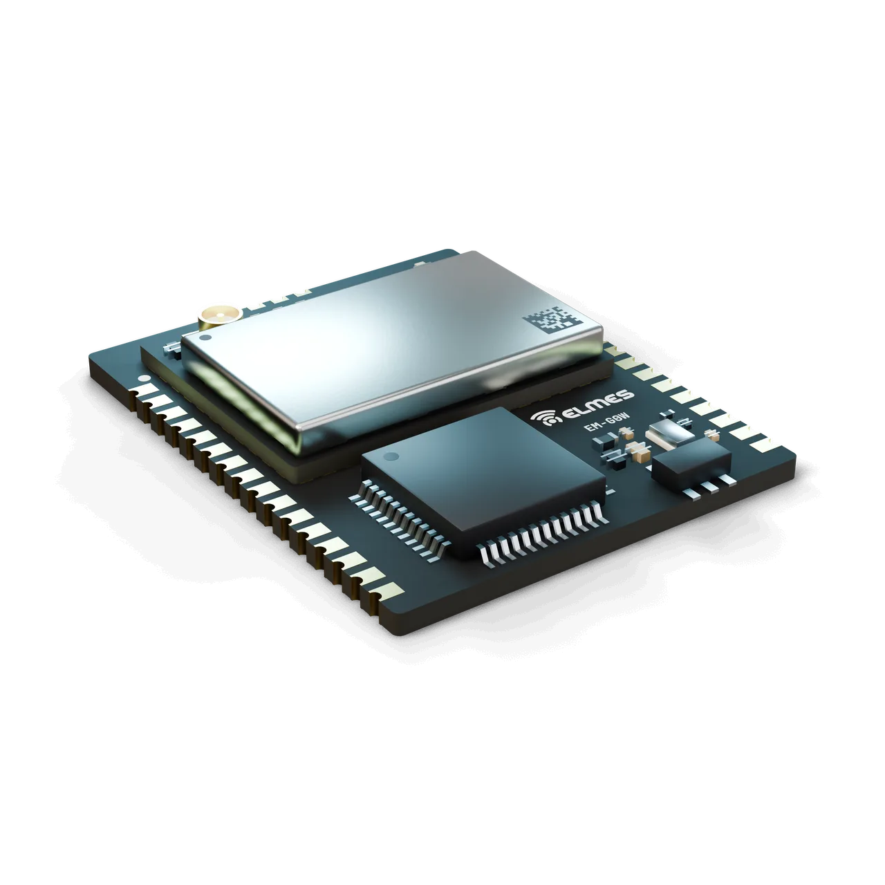
EM-G0WComing soon

STM32 + ESP32 Module (EM-G0W)

Connect your machine to Wi-Fi and keep control on the STM32.

EM-G0W: MCU and Wi-Fi/BLE submodule on one castellated board, with a u.FL antenna connector

The problem. The usual way to add Wi-Fi to OEM devices is to move the entire application onto the ESP32. That ties real-time control to the timing of the Wi-Fi stack, entrusts safety functions (door lock, relay cut-off, E-Stop) to the stability of the wireless chip, and means rewriting ESP firmware for every project. In Elmes's own projects, ESP8266/ESP32 bridges had also been rewritten three times with separate code.

The solution. EM-G0W combines two processors in one module with a clear division of roles. The STM32G0 runs the application, I/O and safety logic; the ESP32 is only a “modem”: Wi-Fi client/AP, BLE, HTTP/MQTT client, local web configuration page and OTA transfer. The two talk over a standard UART frame protocol, which the SDK exposes on the STM32 side like a socket/request API. The ESP firmware is versioned by Elmes; the customer never has to touch ESP code.

Documentation burden. The modular RED/FCC approval declared by the ESP32 module manufacturer reduces the documentation burden on the 2.4 GHz side. For applications that need both LoRa and Wi-Fi, EM-G0LW-433 uses the same bridge protocol.

  • Web configuration + captive portal: AP mode at first setup; standard Elmes page (network, MQTT, device name, firmware).
  • Two-way OTA: the STM32 application through the ESP (Wi-Fi/HTTP); the ESP firmware through the STM32 (UART pass-through) or its own HTTP OTA.
  • ESP power gate: separate LDO + ESP_EN for the ESP; the application can switch Wi-Fi off and put the STM32 into STOP mode.
  • Role lock: the ESP firmware drives no GPIO; all I/O stays on the STM32 (for safety reasons).
  • TargetStandard UART bridge protocol (EM-SDK Open): frame = SOF · length · type · sequence no. · payload · CRC-16. Types: configuration (SSID/password/IP/MQTT), status/event (connection, RSSI, IP), socket (TCP/UDP open-send-receive-close), MQTT (connect/publish/subscribe), HTTP request, BLE GATT characteristic read/write, OTA, time (SNTP). RTS/CTS flow control; event notification via HOST_INT. The same protocol is used on EM-G0LW-433 and, later, on the MOD-M0 USART3 bridge.
  • TargetBLE configuration service: entering Wi-Fi credentials from a phone.
Full specifications and FAQ: STM32 + ESP32 Module (EM-G0W)
Variants and related members
Model codeMCUESP moduleUSBNoteRequest information
EM-G0WSTM32G071CBT6 (first build) → G0B1CBT6ESP32-C3-MINI-1UG0B1 version onlyMain memberRequest information: EM-G0W
EM-G0LW-433G071 / G0B1Same + SX1268 LoRaG0B1Separate PCB; gateway coreRequest information: EM-G0LW-433
EM-G0NG071 / G0B1—G0B1No radio; same footprintRequest information: EM-G0N
Radio — Wi-Fi / BLE
Frequency band2400–2483.5 MHz (Wi-Fi 802.11 b/g/n, BLE 5)
ChannelsWi-Fi 1–13 (regional setting); BLE 40
Output powerWi-Fi ≈ +20 dBm class, BLE ≈ +20 dBm class (Espressif datasheet)
Receiver sensitivity≈ −97 dBm @ 11b 1 Mbps (ESP32-C3 datasheet)Target
ModulationDSSS/OFDM (Wi-Fi), GFSK (BLE 1M/2M/Coded)
Data rateWi-Fi PHY rate up to 72 Mbps (HT20)
UART bridge limit921.6 kbpsTarget
Antenna connectionu.FL and antenna pin (2.4 GHz); external antenna via the ESP “-1U” version
Range
Indoor (to AP)≥ 30 m (typical office/workshop)Target
Open field≥ 100 m (line of sight to AP)Target
Communication & security
Wi-Fi encryptionWPA2/WPA3-Personal (ESP)
Application-layer securityTLS 1.2 (MQTT/HTTPS); BLE LE Secure pairingTarget
IdentityMCU UID + ESP MAC; device name
Performance & fail-safe
Command latency (local network)< 50 ms (UART bridge + Wi-Fi, local TCP)Target
Fail-safe on link lossApplication-defined; SDK timeout 1–60 s; ESP reset via ESP_EN
Power
Supply3.0–3.6 V (module); 9–36 VDC on the carrier
ESP supplySeparate LDOTarget
Wi-Fi TX peak current≈ 350 mA (Espressif data, approximate)
Consumption with ESP off< 50 µA (STM32 in STOP mode)Target
Architecture
MCUSTM32G071CBT6 → G0B1CBT6; 64 MHz Cortex-M0+, 128/512 KB flash
STM32 ⇄ ESP linkUART (115,200 bps default, RTS/CTS), ESP_EN, ESP_IO0, HOST_INT
Interfaces
Exposed pins (minimum)Series-wide layout: SWD, 2× UART, 1× SPI, 1× I2C, 8× GPIO, 2× ADC, USB (G0B1), NRST, BOOT0; ESP UART internal to the module
ESP_EN / ESP_IO0 padsBrought out to pads for factory flashingTarget
Mechanical & environmental
Pad count / pitch2× 16 castellated, 1.27 mm (series-wide)
Dimensions≤ 20 × 25 mm (series-wide)Target
MountingCastellated SMD; keep-out area on the 2.4 GHz antenna side
Operating / storage temperature−40…+85 °C / −40…+105 °C (ESP module −40…+85 °C)Target
Humidity5–95 %, non-condensing
Warranty & service
Warranty2 yearsTarget
Spare-parts support5 years
ProductionAnkara

In the first phase it is supplied with the note “OEM integrator responsibility”; no certificate has been issued for EM-G0W. The ESP32 module's RED/FCC/IC modular approval and RoHS documents are manufacturer declarations, not Elmes certificates, and are collected during procurement.

  • End-product CE/RED conformity
    OEM integrator responsibility in the first phase
    Out of scope
  • ESP32 module modular approval (RED/FCC/IC)
    Manufacturer's declaration; to be collected and verified during procurement
    Target
  • EN 300 328 (2.4 GHz radio)
    If antenna and layout conditions are kept, the radio tests rely on those of the modular-approved ESP module; an accredited lab's opinion will be obtained
    Target
  • EN 301 489-1/-17 (EMC, complete module)
    Target
  • EN 62368-1 (in product context)
    Target
  • RoHS / REACH declaration
    Target
Why is an STM32 needed when there is an ESP32?

So that control, I/O and safety logic stay independent of the Wi-Fi stack. The machine does not stop when Wi-Fi drops, and relay states do not change while the ESP restarts.

Can I change the ESP firmware?

There is no need: the ESP bridge firmware is versioned by Elmes and the protocol is open (EM-SDK Open). You can load your own image with ESP-IDF, but that falls outside the scope of support.

Can I use the web interface with my own branding?

Yes; the configuration page template is planned to ship in the SDK with a replaceable logo and text.

Does it support MQTT/cloud connectivity?

MQTT and HTTP client commands are planned in the bridge protocol; compatible with Telemetry & Process Intelligence.

Can I use it together with LoRa?

Not on the same module; for LoRa + Wi-Fi there is EM-G0LW-433. Two modules on the same carrier are possible but not recommended.

Can it run on batteries?

Wi-Fi consumption is not suitable for a battery-powered node; short BLE-only use is possible. For a battery-powered LoRa node, there is the EM-G0L-433-LP version.

Does it have CE/RED certification?

The ESP module carries the manufacturer's modular approval (to be verified); certification of EM-G0W as a whole is being done in phases. In the first phase it is supplied under OEM integrator responsibility.

ESP32-C3 or S3?

The ESP32-C3 (ESP32-C3-MINI-1U) was chosen for the bridge role. From the customer's point of view, the pinout and protocol do not change.

EM-G0NComing soon

MCU-Only Core Module (STM32G0)

Same footprint, same SDK — start without a radio and swap the module when you need one.

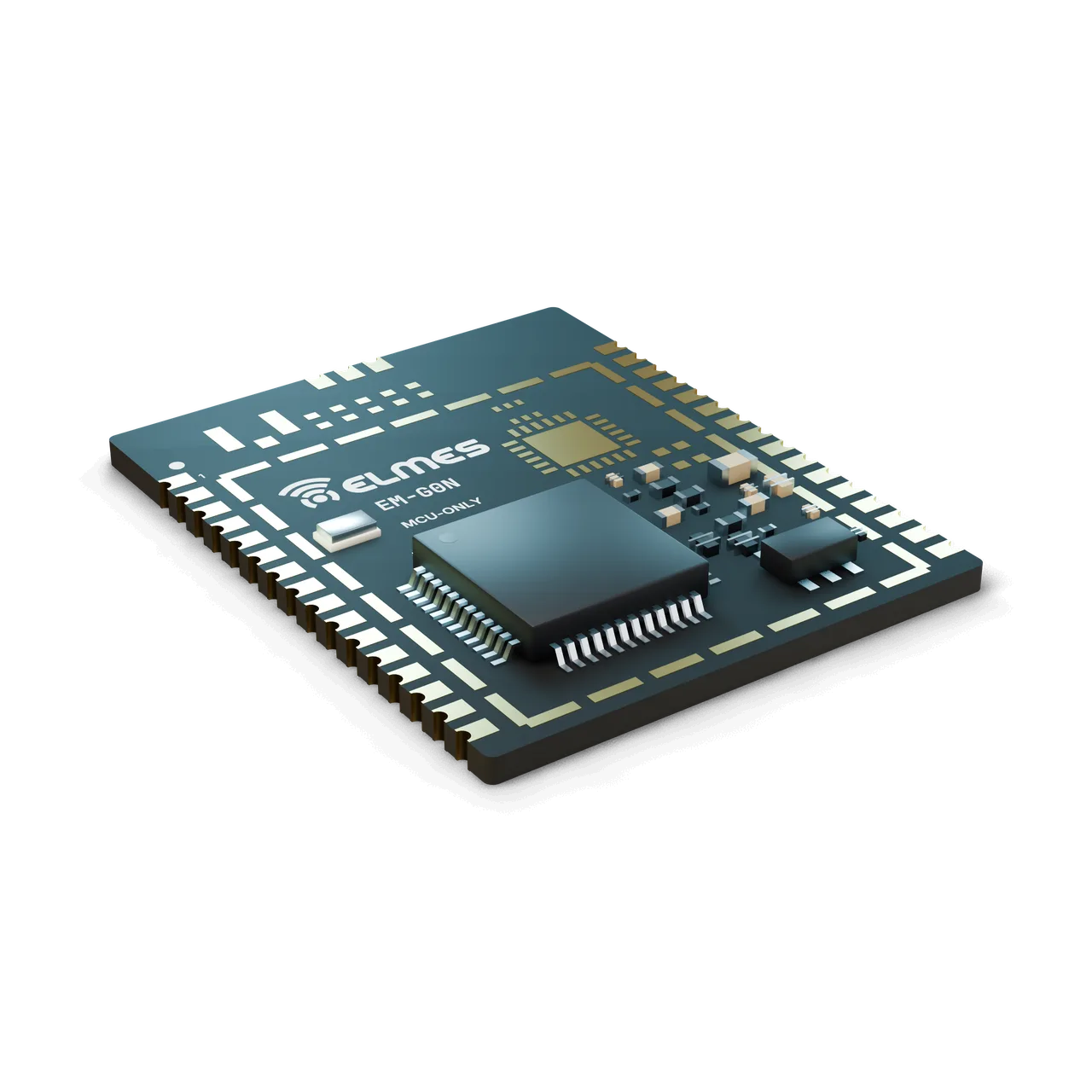
EM-G0N MCU-only core module: unshielded board with exposed MCU and unpopulated radio footprints

The problem. In Elmes OEM projects (OEM Device Control Platform, furnace controller, chiller and lab cabinet controls), every project carries its own main board with its own MCU circuit; four different MCU families (dsPIC33, PIC16F1789, STM32F070, ESP32) have piled up. On every new board the same blocks (power supply, crystal, SWD, bootloader, production programming) are designed again, the firmware infrastructure is rebuilt and the production test is written from scratch. And when a customer asks for wireless, the board gets redrawn.

The solution. EM-G0N offers the MCU core of the module series without a radio. The OEM board carries only the function circuitry (relays, analog, HMI connection, drivers); the MCU, power and programming infrastructure is ready on the module. Because the pad layout is shared by every member of the series, moving the product to a wireless version means swapping the module, not the board. The SDK is the same too: HAL, bootloader, production test protocol and examples all run without a radio; the radio API simply returns “not present”.

Two MCU options. The first build uses the STM32G071CBT6; for boards that need USB-DFU and 2× CAN-FD, an STM32G0B1 version is offered on the same footprint.

  • Pin-compatible upgrade: EM-G0N → EM-G0L / G0W / G0LW / G0C fit the same pads; application code stays on the same SDK.
  • USB-DFU bootloader and 2× CAN-FD on the G0B1 version (with the transceiver on the carrier): PC connection and board-to-board communication on OEM boards.
  • ROM bootloader (G071/G0B1): factory programming over UART/USB via BOOT0; first-time flashing is possible without a fixture.
  • Independent watchdog: IWDG (LSI) and WWDG; the MCU 96-bit UID serves as the hardware ID.
  • Series-wide features: ID/channel programming, OTA infrastructure and telemetry reporting are shared by all EM members.
  • Target2× DAC + 12-bit ADC: on OEM boards with analog outputs (the EC-AIO analog output path), no extra DAC is needed when the on-chip hardware is sufficient.
  • TargetWired OTA: with no radio on board, firmware updates run over UART, USB or RS485.
Full specifications and FAQ: MCU-Only Core Module (STM32G0)
Variants
Model codeMCUUSBCAN-FDRadio padsNoteRequest information
EM-G0NSTM32G071CBT6 (first build)——Not connected (NC)Main memberRequest information: EM-G0N
EM-G0N (G0B1)STM32G0B1CBT6 / CET6USB-FS, DFU2× FDCANNot connected (NC)For OEM boards that need USB/CANRequest information: EM-G0N (G0B1)
Radio
RadioNone; antenna pad not connected (NC)
Communication & security
Device IDMCU 96-bit UID; no AES-128 hardware accelerator (software AES in the SDK)
Firmware signature verificationIn the bootloader (SDK)Target
Performance & fail-safe
Boot time (reset → application)< 50 ms; < 200 ms including the bootloader signature checkTarget
WatchdogIWDG (independent, LSI), WWDG
Power
Supply3.0–3.6 V (module); 9–36 VDC on the carrier
Consumption (run)~100 µA/MHz class @ 64 MHz (datasheet typical)
Consumption (STOP1 / Standby)STOP1 a few µA; Standby < 1 µA (datasheet class)Target
Architecture
MCUSTM32G071CBT6 or STM32G0B1CBT6/CET6; Cortex-M0+ 64 MHz; 128 KB (G071/G0B1CB) or 512 KB (G0B1CE) flash; 36 KB (G071) / 144 KB (G0B1) RAM
Peripherals (G071)4× USART + LPUART, 2× SPI, 2× I2C, 12-bit ADC (2.5 MSPS), 2× DAC, timers, RTC, DMA
Additional peripherals (G0B1 version)USB-FS (device/host), 2× FDCAN, extra USART/I2C
Interfaces
Exposed pins (minimum)Identical to EM-G0L-433: SWD, 2× UART, 1× SPI, 1× I2C, 8× GPIO, 2× ADC, USB (G0B1), NRST, BOOT0
Radio control pins (PA0–PA7)Free inside the module; can be brought out as extra padsTarget
Mechanical & environmental
Pad count / pitch2× 16 castellated, 1.27 mm (common to the series)
Dimensions≤ 20 × 25 mm (same PCB as EM-G0L-433)
Compact size option≤ 15 × 20 mmTarget
MountingCastellated SMD; no keep-out needed (no antenna)
Operating / storage temperature−40…+85 °C / −40…+105 °CTarget
Humidity5–95 %, non-condensing
Warranty & service
Warranty2 yearsTarget
Spare-parts support5 years
ManufacturingAnkara, Türkiye

The module is sold as a component; product-level compliance is the responsibility of the OEM integrator. With no radio on board, RED does not apply. There is no documentation for the module yet; preparation follows the plan below.

  • RED 2014/53/EU
    No radio on the module
    Out of scope
  • EMC — EN 61000-6-2 / -4 or EN 61326 (product level)
    Together with the carrier / OEM board
    Target
  • LVD
    Depending on the carrier supply
    Target
  • RoHS / REACH declaration
    Based on supplier documents
    Target
  • CE declaration of conformity (DoC) template
    Delivered with the SDK package
    Target
Why would I need a module without a radio?

So you don't redesign the MCU infrastructure on every wired OEM board, and so you can move to a pin-compatible wireless member later.

Can I add LoRa later?

Yes: an EM-G0L-433 fits the same carrier; if the antenna path (SMA/u.FL) is left on the carrier in advance, the board does not change.

Does it have USB?

Only on the G0B1 version (USB-FS, DFU). The G071 version uses the UART bootloader.

Does it support CAN-FD?

The G0B1 version has 2× FDCAN; the transceiver sits on the carrier board.

How do I load firmware?

Over SWD (fixture or 4 pins), the ROM bootloader (BOOT0 + UART/USB) or the SDK bootloader; in production, the programming/test fixture is used.

Which SDK and language?

EM-SDK Open (C, Apache-2.0): HAL, bootloader and examples; the radio layer is not compiled in. Details are on the Fixture + SDK page.

Do I need CE documentation?

RED does not apply; EMC and LVD are the integrator's responsibility at product level. Elmes provides a DoC template and compliance preparation support.

Is it cheaper than the wireless members?

With no radio, TCXO or matching network, its bill of materials is lower than the wireless members'; pricing is provided on request.

EM-G0CComing soon

Cellular Module (4G Cat-1 / NB-IoT)

From the field to the cloud in one module — the internet link of your LoRa network.

EM-G0C cellular module: LTE modem submodule, two u.FL connectors, nano-SIM holder and Elmes shield

The problem. Elmes systems (well and tank, Firesens, guard tour, meter reading) run on LoRa in the field; until now, the link to a central computer or the cloud relied on a USB gateway plus a PC/Raspberry Pi, or on project-specific 2G (SIM800) trials. 2G is being shut down, Wi-Fi/Ethernet is not available on every site, and depending on a PC adds maintenance load. Integrating a cellular modem separately into every project (peak current, SIM, antenna, AT command stack, TLS) repeats the same problems each time.

The solution. EM-G0C combines the series' MCU core with an off-the-shelf LTE Cat-1 or NB-IoT/LTE-M modem. The module carries the modem power path (bulk capacitor and regulator for peak current), the SIM slot, the antenna connector and the MCU–modem UART link. The SDK's connectivity layer sets up MQTT/TLS on the modem's internal stack (AT); the application only sees a “publish/subscribe” API.

Ways to use it. On the EC-GW carrier it works side by side with a LoRa module (EM-G0L-433 / EM-G0LW-433) to form the internet end of the Wireless Gateway / RTU; used on its own, it connects a meter or sensor node straight to the cloud.

  • SDK connectivity layer: the AT stack is hidden behind a net_connect / mqtt_publish / mqtt_subscribe / ota_check API.
  • MQTT/TLS inside the modem: TLS runs on the modem's stack rather than a host stack in G071 memory; certificates and keys are loaded at production with an SDK tool.
  • Modem power switch and PWRKEY control: shuts the fitted modem down completely (battery operation, fault recovery).
  • Local buffering: data is stored in flash while the link is down (together with the Gateway / RTU).
  • GNSS (BG95-GNSS version): position reporting for mobile equipment.
  • Dual-radio gateway: EM-G0C + EM-G0L side by side on the EC-GW; a LoRa ↔ MQTT bridge.
  • Series-wide features: ID/channel programming, bootloader and telemetry reporting are shared by all EM members.
  • TargetCommon network API: the same API also covers Wi-Fi (EM-G0W) and Ethernet (EC-GW), so the application never has to be ported.
  • TargetCellular OTA: the bootloader fetches the image over MQTT/HTTPS and verifies its signature.
  • TargetLow-power (-LP) version: NB-IoT PSM/eDRX + MCU STOP mode; battery-powered meter node.
Full specifications and FAQ: Cellular Module (4G Cat-1 / NB-IoT)
Variants
Model codeModem classTechnologyExtraMCUNoteRequest information
EM-G0C-CAT1Quectel EC200 class (LTE Cat-1)LTE Cat-1 + 2G fallback (depending on modem variant)—G071 / G0B1Main member; always-on link, RTU/gatewayRequest information: EM-G0C-CAT1
EM-G0C-NBQuectel BG95 class (LPWA)NB-IoT / LTE-M (+ GNSS, depending on modem variant)—G071 / G0B1Battery-powered / low-data nodes, metersRequest information: EM-G0C-NB
EM-G0C-…-LPTargetAny of the above—Low-Iq power path (shared with EM-G0L-433-LP)—Low-power versionRequest information: EM-G0C-…-LP
Radio
TechnologyCAT1: LTE Cat-1 (+2G fallback, depending on modem variant) · NB: NB-IoT / LTE-M (+GNSS optional)
BandsTR/EU LTE bands (EC200 EU / BG95 multi-band); band list per the selected modem's datasheetTarget
Output powerLTE power class 3: +23 dBm (modem datasheet)
Receiver sensitivityPer the selected modem's datasheetTarget
Data rateCat-1: 10 Mbps DL / 5 Mbps UL (standard upper limit); NB-IoT/LTE-M: tens to hundreds of kbps
Antenna connectoru.FL (LTE); second u.FL on the GNSS version; 50 Ω; for use with the Elmes RF antenna series (700–2700 MHz)
SIMnano-SIM slot (on the module) or on the carrier
eSIMMFF2 versionTarget
Range
CoverageDepends on the operator network; NB-IoT adds deep coverage (indoors / underground)
Communication & security
Transport securityTLS 1.2 (modem's internal stack; certificates loaded with an SDK tool)
MQTT authenticationUsername/password or client certificateTarget
Device IDIMEI + MCU UID; SIM PIN management
Performance & fail-safe
Network registration / first connection< 30 s (Cat-1, cold start); longer on NB-IoT, short when waking from PSMTarget
Behavior on link lossApplication-defined; reconnect backoff 10 s → 10 min
Power
Supply5 V from the carrier; 3.8 V modem rail and 3.3 V MCU rail on the module
5 V rail capacity≥ 1.5 ATarget
ConsumptionTX peak 2 A class @ 3.8 V (LTE, datasheet); tens of µA class in NB-IoT PSM (datasheet); modem power switch on the -LP version
Architecture
MCUSTM32G071CBT6; G0B1 option (USB-DFU, more RAM for a host TLS/MQTT stack)
MCU–modem linkUART (115.2–921.6 kbps), PWRKEY, STATUS, RI, DTR
Modem USB linesNot brought out to padsTarget
Interfaces
Exposed pinsSeries-common 2×16 (SWD, 2× UART, SPI, I2C, GPIO, ADC, USB [G0B1], NRST, BOOT0) + extra pad row (5 V input, external SIM, modem status, GNSS u.FL)
Mechanical & environmental
Pad count / pitch2×16 + extra row, 1.27 mm
Extra pad row1×12Target
Dimensions≤ 30 × 40 mm (depending on the modem LGA size)Target
MountingCastellated SMD; keep-out on the antenna side; thermal pad under the modem
Operating temperature−30…+75 °C (modem datasheet class)
Temperature (MCU side)−40…+85 °CTarget
Humidity5–95 %, non-condensing
Warranty & service
Warranty2 yearsTarget
Spare-parts support5 years
ManufacturingAnkara, Türkiye

The modem is selected with its manufacturer's modem-level certifications (RED in the EU, GCF); there is no documentation for the module yet. In the first phase the module is offered with an “OEM integrator's responsibility” note; using a certified modem is intended to limit product testing to EMC and safety only.

  • Modem manufacturer certifications — RED (EU), GCF, PTCRB
    To be added from the datasheet once the modem is finalized
    Target
  • EMC — EN 301 489-1 / -52 (cellular)
    Target
  • Safety — EN 62368-1
    Target
  • RoHS / REACH declaration
    Target
  • Turkish operator requirements (bands / IMEI registration)
    Requirements being clarified; no compliance claim
    Target
Cat-1 or NB-IoT?

For an always-on link, gateway/RTU use and relatively high data volumes, choose Cat-1 (EC200 class). For battery power, infrequent data and deep coverage, choose NB-IoT/LTE-M (BG95 class).

Is a SIM included?

No; the customer provides the M2M SIM, and the APN is configured through the SDK.

Does it work together with LoRa?

Yes; it sits next to an EM-G0L on the EC-GW carrier, and the SDK provides the LoRa ↔ MQTT bridge (Wireless Gateway / RTU).

Which cloud?

Any broker over MQTT/TLS: Elmes telemetry (Telemetry & Process Intelligence), your own server or public cloud IoT services.

How much power does it need?

LTE transmission draws brief 2 A class current peaks; the carrier needs a 5 V rail rated ≥ 1.5 A plus a bulk capacitor. Battery operation is planned with NB-IoT + PSM.

Can I update the firmware remotely?

Cellular OTA with signed images is planned. In the first release, updates run over UART/USB.

Is the RF design your own?

No; it uses a certified off-the-shelf modem. Elmes provides the power path, SIM, antenna, MCU and software stack.

Is 2G supported?

Depending on the Cat-1 modem variant, 2G fallback may be available; because 2G networks are being shut down, the design relies on LTE.

EM-W5L-433Coming soon

STM32WLE5 Integrated LoRa Module (MCU + radio on one chip)

One chip, one module — MCU and LoRa on the same silicon, on the same Elmes pinout.

EM-W5L-433 single-chip LoRa module: compact nickel shield, RF filter chain and u.FL

The problem. In small battery-powered end devices (buttons, sensors, pagers), a two-chip module (MCU + SX1268) costs board space, BOM and assembly. Imported WLE5 modules (Wio-E5, RAK3172) are cheap and certified, but at 433 MHz they do not fit the Elmes channel plan or pinout; their firmware is AT/LoRaWAN-centric, and supply changes from one revision to the next.

The solution. EM-W5L-433 puts the STM32WLE5 on a module with Elmes' own 433 MHz matching design and the common castellated pinout. The SDK's shared radio driver (SX126x/LLCC68/WL) is built with the WL profile; protocol, bootloader and production test are identical to the G0 members. Fitting a W5L in place of an EM-G0L-433 changes only the MCU profile in firmware (Cortex-M4, different HAL).

Band options. The 868/915 MHz version is built on the same PCB by changing only the matching network and filter; the -LP version for battery-powered nodes, with selectable HP/LP PA, uses the same base.

  • Single-chip MCU + LoRa: no SPI/DIO lines between chips; fewer pads used.
  • HP/LP PA selection in software: +22 dBm for range / +15 dBm for low consumption (battery version).
  • Hardware AES/PKA/RNG: encryption and signature verification without loading the CPU (G0 members use software AES).
  • 868/915 MHz version on the same PCB: only the matching network and filter change.
  • Low-power (-LP) version: the same power-path logic as EM-G0L-433-LP (bypass/low-Iq LDO, battery measurement, WKUP); STOP2 offers potential for lower sleep current.
  • SDK WL profile: the same radio API; build target MCU=wle5.
  • No USB: the bootloader works over UART and OTA; products that need USB use the G0B1-based members.
  • Series-wide features: ID/channel programming, bootloader + OTA and telemetry reporting are shared by all EM members.
  • TargetExtra GPIO: the pins that drive the radio on G0 members are brought out to the pads as free GPIO.
Full specifications and FAQ: STM32WLE5 Integrated LoRa Module (MCU + radio on one chip)
Variants
Model codeMCU / radioBand / matchingPA pathNoteRequest information
EM-W5L-433STM32WLE5CCU6 (256 KB flash, 64 KB RAM, UFQFPN48); alternative WLE5CBU6 (128 KB)433 MHz matching (Elmes design)HP (+22 dBm)Main memberRequest information: EM-W5L-433
EM-W5L-868 / -915SameSX1262 equivalent; 868/915 MHz matchingHPBand versionRequest information: EM-W5L-868 / -915
EM-W5L-433-LPSameSameHP/LP selectableBattery-node version (EM-G0L-433-LP power-path logic)Request information: EM-W5L-433-LP
Radio
Frequency band150–960 MHz (STM32WL datasheet); Elmes channel plan 433.05–434.79 MHz (same 8 channels as EM-G0L-433)
Channels8 (EM-G0L-433 plan), 200 kHz spacing, 125 kHz BW
Output powerHP PA +22 dBm; LP PA +15 dBm (datasheet); adjustable
Receiver sensitivitySX126x class: −129 dBm @ SF11/BW125 (datasheet)Target
ModulationLoRa (SF5–SF12), (G)FSK, (G)MSK, BPSK (datasheet)
Data rate0.018–62.5 kbps in LoRa; higher in FSK (datasheet)
Antenna connectionu.FL and castellated antenna pin, 50 Ω
Range
Open field / indoors≥ 2000 m (SF9) / ≥ 300 m; same as EM-G0L-433Target
Communication & security
EncryptionAES-128-CCM; hardware AES on the WLE5 (datasheet) + PKA; NetID + address + UID
Systems on the same site≥ 8 (channel × NetID)Target
Performance & fail-safe
Command latency< 100 ms (SF7)Target
Fail-safe on link lossApplication-defined; SDK timeout 1–60 s
Power
Supply3.0–3.6 V (module); chip 1.8–3.6 V; direct battery supply on the -LP version
Consumption (RX / sleep)RX ~5 mA class; STOP2 ~1 µA class + radio sleep (datasheet)
Consumption (TX @ +22 dBm)Lower than an SX1262-based designTarget
Architecture
MCUSTM32WLE5CCU6: Cortex-M4 48 MHz, 256 KB flash, 64 KB RAM, UFQFPN48
Peripherals2× USART + LPUART, 2× SPI (one is the internal SUBGHZSPI), 2× I2C, 12-bit ADC, DAC, LPTIM, RTC, AES/PKA/RNG; no USB
Interfaces
Exposed pinsSeries-common: SWD, 2× UART, 1× SPI, 1× I2C, 8× GPIO, 2× ADC, NRST, BOOT0; USB pads not connected (NC)
Extra GPIOOn the pads that carry the radio pins on G0 membersTarget
Mechanical & environmental
Pad count / pitch2× 16 castellated, 1.27 mm
Dimensions≤ 20 × 25 mm; smaller is possibleTarget
MountingCastellated SMD; antenna keep-out; 4-layer PCB (RF)
Operating / storage temperature−40…+85 °C / −40…+105 °C (chip −40…+105 °C)Target
Humidity5–95 %, non-condensing
Warranty & service
Warranty2 yearsTarget
Spare-parts support5 years
ManufacturingAnkara, Türkiye

There is no documentation for the module yet; certifications follow the series plan in stages (after EM-G0L-433 and EM-NL-433). Certificates of comparable imported modules (Wio-E5, RAK3172) cannot be transferred to the Elmes module; Elmes' own measurements are required. Because the 433 MHz matching is an Elmes design, in-house pre-compliance measurements come first.

  • In-house pre-compliance measurement (harmonics / spurious)
    Before accredited lab testing
    Target
  • CE – RED 2014/53/EU: EN 300 220-2 (radio)
    Target
  • EN 301 489-1 / -3 (EMC)
    Target
  • EN 62368-1 (in the product context)
    Target
  • RoHS / REACH declaration
    Target
When should I pick the W5L over the EM-G0L-433?

For end devices that need no USB and where size, cost and battery life are critical. If you need USB, CAN-FD or many UARTs, choose a G0 member.

Does it work in the same network as the EM-G0L-433?

Yes; the protocol core and channel plan are identical, and the difference in silicon stays inside the module.

Can firmware be ported from G0?

At source level, yes (the SDK API is the same); it is a separate build target (Cortex-M4, WL HAL).

How is it different from Wio-E5 / RAK3172?

The 433 MHz Elmes matching and channel plan, the common Elmes pinout, EM-SDK in place of an AT/LoRaWAN stack, and local support. Their certificates focus on 868/915 MHz and belong to their own modules.

Does it have USB?

No; updates go through the UART bootloader and OTA. Carriers that need USB use the G0B1-based members.

Is 868 MHz available?

The EM-W5L-868 / -915 version is built on the same PCB by changing only the matching network.

Does it support LoRaWAN?

It is not a design goal; the module runs the Elmes protocol. A LoRaWAN stack (LoRaMac-node) exists for the chip and can be considered under EM-SDK Pro or a project-based development (NRE) agreement.

Is it cheaper than the EM-G0L-433?

Being single-chip, it is expected to cost less; pricing is provided on request.

Applications

  • Machine builders (wireless remotes/receivers)
  • Agricultural and irrigation equipment
  • Water utility integrators
  • Building and facility automation
  • Meter reading
  • Fire/security panel manufacturers
  • Gateways and telemetry nodes
  • Academic and prototype use

In Elmes products. The module family was designed as the core of Elmes products:

AreaElmes productModule
Water/well and tank, pump, valve controlWell & Tank Control, Irrigation Control, Digital I/O LinkEM-G0L-433 + EC-DIO8
Analog/digital data transfer, telemetry nodeAnalog & Digital Data Transmitter, Meter Reading NodeEM-G0L-433 + EC-AIO / EC-PLS
Fire and security end devicesFiresens Fire Alarm, Guard Tour ControlEM-G0L-433; EM-G0L-433-LP in battery-powered buttons
Call and remote control (waiter, taxi, pager)Waiter Call, Taxi Call, WR-001, Call ButtonEM-G0L-433-LP
Crane and machine control (split architecture)Crane Control, Machine ControlEM-NL-433 + existing MCU
Wireless RS485/Modbus bridgeRS485 ModemEM-G0L-433 + EC-485
Gateway / RTU, cloud connectivityGateway / RTU, Telemetry & Process IntelligenceEM-G0LW-433, EM-G0C
OEM device control, wired boardsOEM Device Control Platform, Thermal Process ControllerEM-G0N, EM-G0W
Sensor nodesSmart SensorsEM-G0L-433-LP, EM-W5L-433

External OEM fields. Machine builders (wireless remotes/receivers), agricultural and irrigation equipment, water utility integrators, building/facility automation, meter reading, fire/security panel manufacturers, academic and prototype use.

In the field. MOD-M0, the first member of the family, is running in the field in Elmes well and tank control and Firesens fire alarm products.

Compliance & documentation

In the first phase, the modules are supplied with the note “OEM integrator responsibility”: the manufacturer that integrates the module into its product is responsible for the conformity assessment of the end product. Module-level documentation is being obtained step by step in the order below; no module-level certificate has been issued yet.

  • End-product CE/RED conformity
    OEM integrator responsibility in the first phase
    Out of scope
  • Module-level pre-compliance measurements (output power, harmonics, bandwidth, spurious emissions)
    With Elmes equipment; internal test report and a “measured” mark in the datasheet
    Target
  • CE – RED 2014/53/EU: EN 300 220-2 (radio), EN 301 489-1/-3 (EMC)
    At an accredited lab; EM-G0L-433 first, then EM-NL-433. Once the radio-only module is certified, the radio part can carry over to derivative products.
    Target
  • Electrical safety: EN 62368-1 or EN 61010-1
    Depending on the product context
    Target
  • RoHS / REACH declaration
    Based on supplier documentation
    Target
  • CE declaration of conformity (DoC) template
    Included in the SDK package
    Target
  • Separate EN 300 220 testing for the 868 MHz variants
    Target

Frequently asked questions

How many systems can run on the same site without interfering?

Systems are separated by a combination of channel, address and spreading factor; in LoRa, different SFs do not see each other. At least 8 independent networks are targeted through channel × network ID; the exact number will be determined by measurement.

How does it differ from an off-the-shelf Far East module?

An open SDK, a fixed pinout, local support in Turkish and a radio path proven in Elmes products. Imported off-the-shelf modules usually have closed firmware, and their pinout and supply can change from one revision to the next.

Can I use only the radio with my own MCU?

Yes: EM-NL-433 is a radio-only module with an SPI interface.

Is 868 MHz available?

Yes, as SX1262 band variants (EM-G0L-868 / -915, EM-NL-868); the ETSI duty-cycle rules are implemented in the SDK.

Do the modules have CE/RED certification?

In the first phase, the modules are supplied under OEM integrator responsibility; module-level RED certification is being obtained step by step. The order is shown in the compliance section of this page.

How long does the battery last in a battery-powered device?

It depends on the transmit interval and the spreading factor. A battery-life calculator is planned for the SDK; values will be published together with measurements.

Is the firmware source code provided?

Yes. The open SDK (Apache-2.0, planned) includes the HAL, radio driver, bootloader, protocol core and examples. Elmes's own product application layer, network profiles (repeater/mesh), fleet/OTA server tools and production scripts are separate (Pro). Details are on the fixture and SDK package page.

Is it compatible with the earlier MOD-M0?

Software yes, footprint no: MOD-M0 uses a pin header, the new series is castellated. An adapter carrier for migration is planned.

Get information about this product

Our engineering team replies within 24 hours.